





Split-Board USB Camera Module for Flexible Camera Placement

$1.00

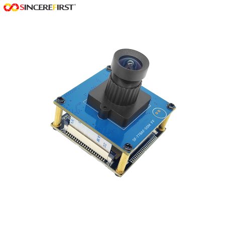
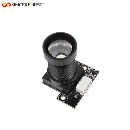
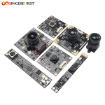
USB camera module with integrated microphone, separate camera board design, FPC connection, USB connector and compact 30 × 18mm main PCB.

—————————————————————————————–
Price is for reference only. Please contact us for the latest quotation.

+ −
  • Cmos UVC USB Camera Module Industrial Camera Module

    Split-Board USB Camera Module for Flexible Camera Placement
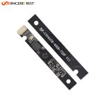
    $1.00

    Request a Call Back

    • Cmos UVC USB Camera Module Industrial Camera Module

      Split-Board USB Camera Module for Flexible Camera Placement

      $1.00

      Ask a Question

        ... people are viewing this right now

        Share
      Cmos UVC USB Camera Module Industrial Camera Module

      Introduction

      In some embedded products, the lens has to fit into a very small front opening, while a complete USB camera PCB cannot be placed directly behind it.

      This camera module solves that mechanical problem by separating the camera head from the USB processing board. The compact camera board can be positioned close to the viewing window, while the larger main PCB can be placed elsewhere inside the enclosure and connected through FPC.

      The main board also integrates a microphone, making this architecture suitable for products that need both video and audio while keeping the actual camera head as small as possible.

      Applications in Real Devices

      Thin-Bezel Display Devices

      A narrow display bezel may have enough room for the lens and small camera board but not for a complete USB processing PCB.

      The split-board structure allows the camera head to remain near the bezel while the main board is moved deeper into the device.

      Compact Smart Terminals

      Some terminals have restricted front-panel space but more internal room behind or beside the display.

      Separating the optical section from the USB main board gives the mechanical design more freedom than a one-piece camera module.

      Embedded Audio-Video Equipment

      The main PCB includes a microphone position together with the USB and FPC connections.

      This allows the device to combine camera and audio functions while keeping the optical head physically separate.

      Custom Enclosures with Remote Camera Placement

      Products with unusual internal geometry may require the lens to sit away from the main electronics.

      A camera-head-plus-FPC architecture provides more flexibility for routing the imaging section to the required position.

      Project Evaluation Guide

      Consider This Model When

      • The camera head must fit into a very small front area.
      • The USB processing board can be placed elsewhere inside the device.
      • A split-board camera architecture is preferred.
      • FPC routing is possible inside the enclosure.
      • Integrated microphone functionality is useful.
      • A rectangular 30×18mm main PCB fits the internal space.
      • Camera and main-board placement need to be designed independently.

      Confirm Before Sampling

      • Available space at the camera opening.
      • Available space for the main USB PCB.
      • Required distance between the camera board and main board.
      • FPC length and bending path.
      • Lens FOV and working distance.
      • Required resolution and frame rate.
      • Microphone opening and acoustic path.
      • USB host requirements.
      • Connector orientation and assembly method.

      Choosing This Model Within the USB Camera Module Series

      This model represents the split-board USB camera direction.

      Choose it when the mechanical design cannot place a complete camera PCB directly behind the lens.

      Compared with the integrated SF-C1014USB-2020-MIC, this model separates the camera head from the USB main board. That gives the enclosure designer more freedom to place the optical section in a smaller opening.

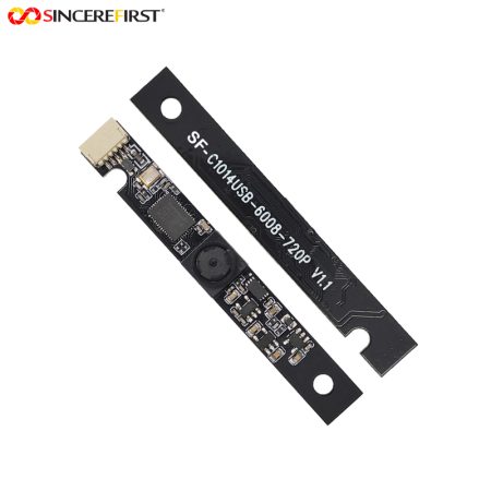
      Compared with the SF-C1014USB-6008-720P, which solves narrow-space integration through a long 60×8mm PCB, this model solves the problem differently: it uses two physically separated boards rather than one elongated board.

      Related Models

      SF-C1014USB-2020-MIC V1.0
      Consider this model when a one-piece 20×20mm USB camera with integrated microphone can fit directly behind the lens opening.

      SF-C1014USB-6008-720P V1.0
      Consider this model when the enclosure provides a long, narrow mounting area and a single-board 60×8mm structure is preferred.

      Key Specifications

      SpecificationDetails
      Product NameSplit-Board USB Camera
      ModelSF-C1014USB-SW01 V1.0
      StructureSeparate Camera Board + USB Main Board
      Main PCB SizeApprox. 30 × 18mm
      Camera BoardCompact Separate PCB
      Camera ConnectionFPC
      FPC Connector24Pin Structure
      USB Connector5Pin Structure
      AudioIntegrated Microphone on Main Board
      Main PCB ThicknessApprox. 1mm
      VersionV1.0


      SincereFirst Customization

      Camera Board and Lens

      The camera-head size, lens FOV and focus configuration can be evaluated according to the front opening, working distance and required viewing area.

      FPC Length and Routing

      FPC length, connector orientation and bending direction can be evaluated according to the distance between the camera head and main PCB.

      Main PCB and Microphone Layout

      Main-board dimensions, mounting position and microphone placement can be reviewed according to the enclosure and acoustic opening.

      USB and Connector Integration

      USB connector direction, cable structure and host-side integration can be evaluated according to the final system architecture.

      Final configuration should be validated with the actual host platform, enclosure, optics, software, and lighting environment before sampling.

      FAQ

      Why use a split-board camera instead of a normal USB camera module?

      A split-board design is useful when there is not enough space directly behind the lens for the complete USB PCB.

      The small camera head can remain at the viewing window while the processing board is moved to another location.

      Does the FPC length affect the design?

      Yes.

      Cable length, bending, routing and connector position should all be evaluated because they affect mechanical assembly and signal integration.

      Is the camera head smaller than the main PCB?

      Yes.

      The drawing clearly separates the small optical board from the larger 30×18mm USB main board, which is the main reason for this architecture.

      Is the microphone located on the camera head?

      No.

      The combination drawing places the microphone on the main USB PCB rather than on the separate camera board.

      Can the camera board be positioned at a different angle from the main PCB?

      Potentially, because the two sections are linked through FPC rather than being one rigid PCB. The actual orientation still needs to be validated against FPC bending and enclosure constraints.

      What resolution and frame rate does this model support?

      The current one-page mechanical drawing does not specify resolution or frame rate.

      Those parameters should be confirmed from the corresponding electrical specification before publishing them.

      Request Project Evaluation

      If your device has very limited space around the camera opening but more room elsewhere for the USB electronics, share the available camera-head area, main-board space, required FPC length, working distance and host requirements.

      SincereFirst can evaluate whether a split-board USB architecture is more suitable than a one-piece camera module.

      Send Inquiry

        Close
        Close My Cart
        Close Recently Viewed
        Close
        Close
        Categories