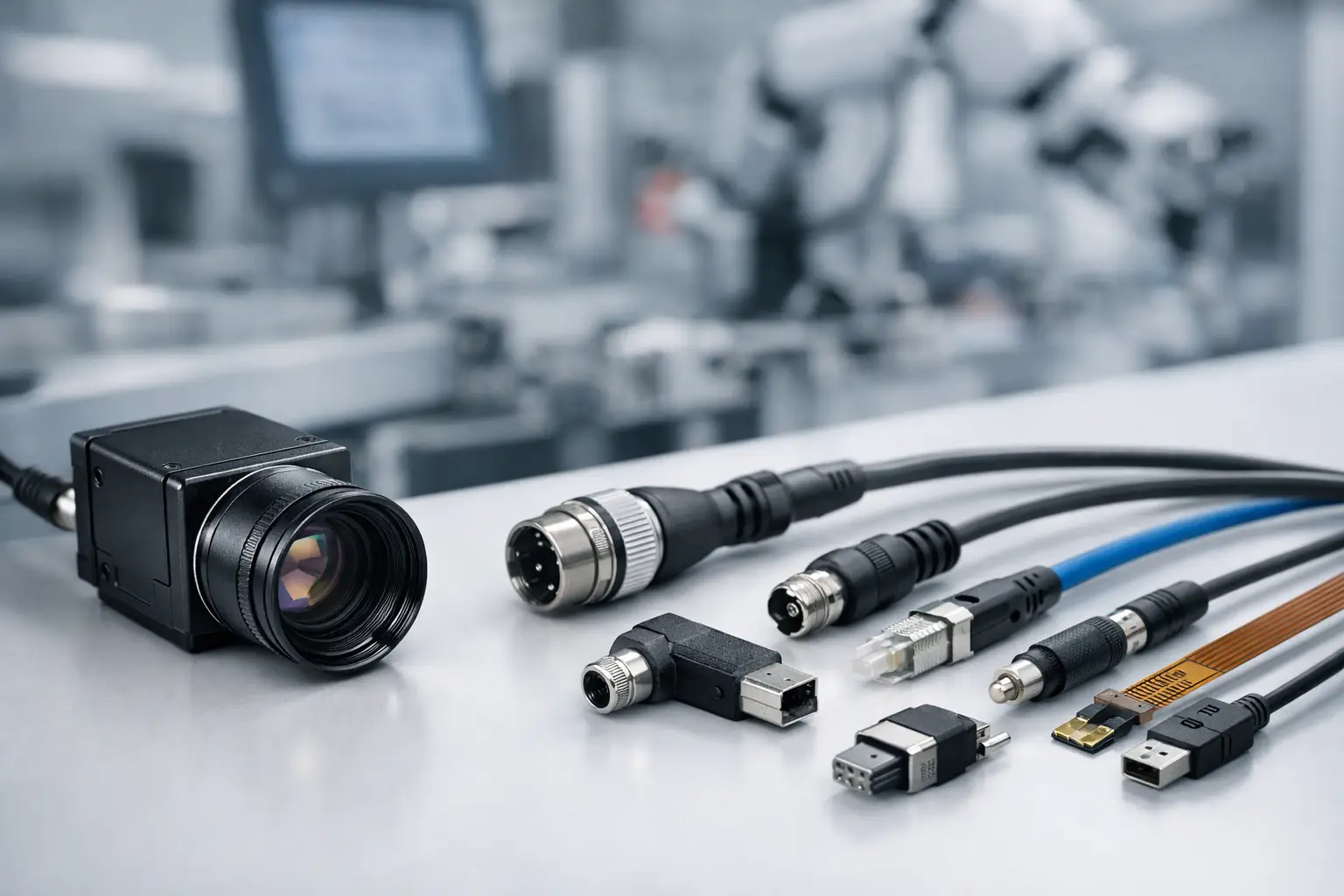
A camera module can meet every imaging target on paper and still fail in the field because of one overlooked detail – the connector. In industrial systems, connector choice affects signal integrity, cable routing, vibration resistance, serviceability, and long-term uptime. This industrial camera connector selection guide is written for engineers, sourcing teams, and product developers who need to make the right decision early, before a connector becomes the weak point in an otherwise capable vision system.
Why connector selection matters in industrial vision
Industrial cameras do not operate in lab conditions for long. They end up inside robots, inspection tools, access systems, handheld devices, agricultural equipment, medical instruments, and embedded edge AI products. In each case, the connector has to do more than pass a signal. It has to survive motion, contamination, thermal cycling, repeated assembly, and the realities of production tolerances.
That is why connector selection is not just a mechanical detail. It is part of system architecture. The wrong connector can introduce intermittent dropouts, EMI issues, cable strain problems, and expensive redesigns after validation. The right connector supports stable image transmission, easier assembly, and scalable manufacturing.
Start with the interface, not the connector shape
A useful industrial camera connector selection guide should begin with the signal standard. Many teams start by looking at connector size, lock type, or cable direction. Those factors matter, but they come second. First define what the camera needs to transmit and how the host system will receive it.
For embedded imaging, common interfaces include MIPI CSI-2, USB 2.0, USB 3.0, DVP, LVDS, and custom board-to-board designs. Each one has different bandwidth, pin mapping, shielding, routing, and cable length limits. A compact FPC connector may work well for a short internal MIPI connection inside a sealed device, but it is usually a poor fit for an exposed industrial cable that sees vibration and operator handling.
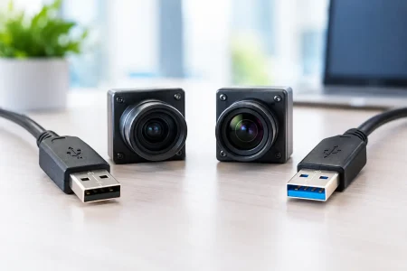
USB-based camera modules often simplify software integration and interoperability, especially when UVC support is required. But USB connectors must still be evaluated for retention force, mating cycle life, and shielding effectiveness. MIPI connectors can support high-performance embedded designs in a small footprint, but they demand careful control of cable length, impedance, and assembly conditions.
Match the connector to the installation environment
The operating environment should narrow your options quickly. A stationary inspection camera mounted in a sealed enclosure has different connector demands than a mobile robot camera, an industrial endoscope, or a medical imaging device.
Vibration is one of the first filters. Friction-fit connectors are compact and cost-effective, but in high-motion environments they may require additional mechanical retention or enclosure support. Locking connectors add stability, though they also increase package size and assembly steps. If the camera is mounted on moving equipment, connector retention should be treated as a reliability requirement, not a convenience feature.
Dust, moisture, chemicals, and cleaning methods also matter. In some applications, the actual board-level connector is protected inside the housing, so the external cable assembly carries the environmental burden. In others, the connector itself must tolerate exposure. That changes material selection, sealing strategy, and plating requirements.
Temperature adds another layer. Thermal expansion can affect contact reliability, especially in compact assemblies with fine-pitch connectors. If the product will cycle between low and high temperatures, connector housing stability and cable strain relief deserve closer review during validation.
Electrical performance is where many failures begin
Mechanical fit is easy to see. Signal quality problems are not. High-speed image data is sensitive to connector design, pin layout, grounding strategy, and cable construction. At higher data rates, a connector is not just a contact point. It becomes part of the transmission path.
Differential pair routing must remain controlled through the connector and cable assembly. Impedance mismatch can degrade image quality or create unstable links that only fail under certain operating conditions. EMI susceptibility can show up when motors, power supplies, or RF subsystems are active nearby. In tightly packed industrial equipment, that is common.
Power delivery is equally important. Some camera modules draw modest current, while others include IR, autofocus, onboard processing, or active illumination that increases power demand. The connector must support both the signal and the required current without excessive voltage drop or heat buildup. Engineers should also check pin assignment carefully. A connector that looks suitable mechanically may not provide the grounding or power isolation needed for stable operation.
The real trade-off: compactness vs durability
Connector selection is often a trade between miniaturization and field reliability. Small connectors help reduce module size and support slim product designs. They are often the right choice in handheld electronics, compact embedded systems, and tightly integrated machine vision assemblies.
But smaller connectors usually demand more from the manufacturing process. Fine-pitch contacts are less forgiving during assembly. Cable handling becomes more delicate. Rework can be harder. If the product will be serviced in the field or assembled in high volume across multiple lines, that trade-off needs to be made intentionally.
Larger locking connectors take more space, yet they often improve cable management and installation confidence. For industrial equipment expected to run for years with minimal intervention, the additional size may be worth it. There is no universal best option here. The better question is whether the product is optimized for density, serviceability, or long-term mechanical stability.
Industrial camera connector selection guide for common use cases
For internal board-level camera connections, FPC or board-to-board connectors are often the most efficient choice. They fit well in embedded devices where cable runs are short, controlled, and protected. This is common in compact automation products, smart terminals, medical handhelds, and custom vision modules integrated directly into a host PCB.
For external camera modules or systems that need simpler host integration, USB connectors remain practical. USB 2.0 is often sufficient for lower-bandwidth imaging, while USB 3.0 supports higher resolution and frame rate requirements. The advantage is development speed and broad compatibility. The trade-off is that cable quality and connector retention become more critical as performance increases.
For custom industrial systems, especially where the camera, cable, and host board are all being designed together, tailored connector solutions can solve packaging and reliability problems that standard interfaces cannot. This is often the right path when products need unusual cable lengths, constrained housing geometry, or application-specific sealing.
Think about assembly and scale before finalizing the design
A connector that works in prototype quantities may not work well in mass production. That is where many sourcing and engineering teams run into avoidable delays. Connector orientation, insertion force, cable bend radius, and operator access all affect assembly time and defect rates.
If the connection is difficult to align or easy to damage, yield can drop as production scales. If the cable exits at the wrong angle, the enclosure may need to be changed. If the connector requires manual reinforcement or adhesive support, cycle time increases. These issues are manageable, but they should be discovered during DFM review, not after pilot production starts.
This is one reason experienced camera module manufacturers put connector selection into the broader integration process. At SincereFirst, connector decisions are typically reviewed alongside sensor choice, module size, lens stack, PCB layout, cable design, and end-use environment because they affect the whole imaging system, not just one interface point.
Questions to ask before you choose
A reliable selection process usually comes down to a few practical questions. What interface bandwidth is required? Will the connector be internal or exposed? How much vibration will the product see? Is field service expected? What is the maximum cable length? How many mating cycles are realistic? Does the camera need custom pinout, shielding, or locking features?
If any of those answers are still unclear, connector selection is probably being made too early. It is better to confirm environmental and system requirements first than to redesign around a connector that looked convenient at the concept stage.
Validation should simulate the real product, not just the bench test
Connector performance should be verified under realistic mechanical and electrical conditions. That means testing with the actual cable routing, housing constraints, power profile, and nearby noise sources. A camera that streams correctly on an open bench may behave very differently after enclosure compression, motor startup, or thermal soak.
Validation should include repeated insertion if serviceability matters, vibration testing if the application is mobile or industrial, and image stability checks at full data rate. If the connector is carrying both power and high-speed data, monitor both. Intermittent image loss is often a system-level symptom of connector weakness rather than a sensor or ISP problem.
The best connector choice is rarely the smallest, cheapest, or most familiar option. It is the one that supports the camera interface, fits the enclosure, survives the environment, and scales cleanly into production. When connector selection is handled with the same discipline as sensor and optics selection, industrial vision systems become easier to build and harder to break.
Choose the connector as if it will be blamed for every failure in the field, because sooner or later, it probably will.