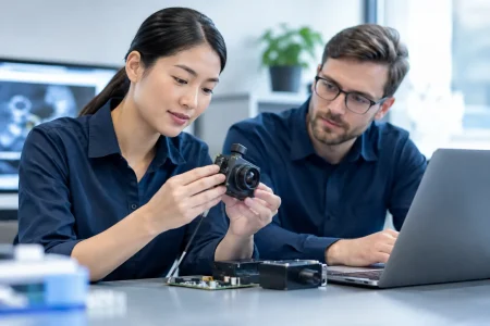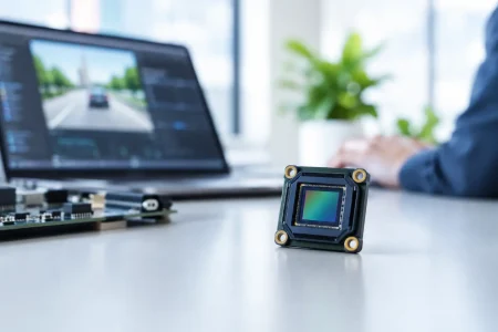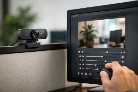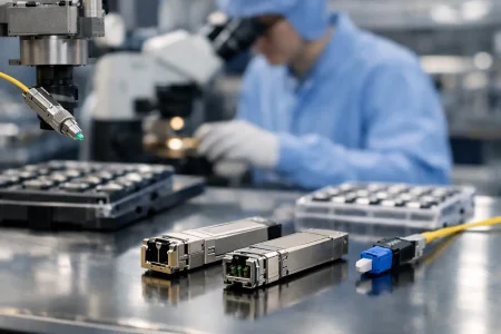
A surgical device imaging integration example is most useful when it shows more than a camera mounted inside a housing. The real engineering task is coordinating optics, illumination, signal transport, processing, thermal limits, mechanical assembly, and clinical workflow within a device that must remain compact and manufacturable. For medical device teams, the camera module is a critical subsystem, but it must be specified in the context of the complete imaging path.
Consider an illustrative single-use minimally invasive visualization instrument. The device needs to provide live color video from a narrow distal tip to a reusable display controller, helping clinicians observe anatomy during a procedure. Its design team wants a small form factor, repeatable image quality, a controlled bill of materials, and a development path that can move from functional samples to volume production.
A Surgical Device Imaging Integration Example in Practice
In this example, the distal assembly contains a compact CMOS camera module, a lens stack, and two micro LEDs positioned around the optical window. A low-profile flex cable carries image data and power through the instrument shaft to a proximal electronics board. That board connects to a processing unit that performs image signal processing, controls LED brightness, and sends a standard video feed to the clinical display.
The architecture sounds straightforward. It is not. Each choice affects the other choices. A sensor with higher resolution may increase data bandwidth and processor load. Brighter LEDs can improve exposure at the target but add heat near the distal tip. A longer flex cable can simplify mechanical routing while increasing susceptibility to signal loss or electromagnetic interference. Successful integration starts by setting priorities rather than selecting components independently.
For a device intended to show tissue surfaces at close range, the team might define a target of 1080p video at 30 frames per second, consistent color reproduction, low visible noise under LED illumination, and acceptable motion response. Depending on the use case, a lower-resolution sensor may still be the better commercial decision if it reduces cable complexity, power consumption, and total system cost without compromising the required clinical view.
Distal Imaging Assembly
The distal imaging assembly determines what the system can actually see. It includes the sensor, lens, cover window, LED placement, adhesive strategy, and mechanical alignment features. In a narrow device, the optical center, field of view, and working distance must be considered together. A wide-angle lens may help maintain orientation in a confined space, but edge distortion can become more noticeable. A narrower lens can provide more detail in the central field, yet may make navigation harder.
For this example, the engineering team selects a compact camera module with a MIPI CSI-2 output, selected for its high-speed digital interface and support from the chosen processor platform. The module is integrated with a lens matched to the required close-focus range. A hydrophobic or anti-fog treatment on the optical window may be evaluated where condensation or fluid exposure could degrade visibility, but coating selection requires compatibility testing with the intended sterilization, packaging, and use conditions.
Mechanical tolerances matter as much as optical specifications. A small angular shift between the lens and sensor can reduce edge sharpness or move the intended field of view. The camera module supplier should be able to support optical alignment control, stable lens fixation, and inspection criteria that are appropriate for the device program. For high-volume products, teams should also define how module orientation, flex exit direction, and connector position will support automated or repeatable final assembly.
Illumination and Thermal Design
Illumination is often the first source of image inconsistency in compact surgical instruments. Two LEDs mounted near the camera can create a useful field of light, but their spacing, emission angle, color temperature, and drive current affect shadows, glare, and color rendering. Too much light can clip highlights on wet tissue. Too little light forces the sensor to increase gain, producing noise and reducing usable detail.
The processor board in this example uses closed-loop or preset LED drive settings for different operating conditions. Exposure and white balance are tuned against the selected LED spectrum rather than left entirely to default camera settings. This helps the final device produce a more consistent image from unit to unit.
Thermal management must be validated early. The LEDs, sensor, and nearby electronics all create heat, while the small enclosure limits heat dissipation. Engineers should measure temperature at the component level and at accessible device surfaces during worst-case operating periods. Reducing LED current, adjusting duty cycle, adding a thermal conduction path, or changing the optical design can all be valid solutions. The best answer depends on the required brightness, procedure duration, device geometry, and allowable power budget.
Signal Path and Processing Requirements
The imaging path begins at the sensor and ends at the display, but every stage can introduce a failure mode. In the example device, the MIPI camera module sends data over a carefully designed flex assembly to a proximal board. The board layout controls impedance, protects sensitive signal lines, and separates camera data paths from LED power circuits where possible.
A flexible printed circuit is not simply a cable. Its length, layer structure, bend radius, shielding approach, and termination design need to match the interface and the mechanical movement expected during assembly and use. If the device shaft must articulate or pass through a tight bend, the FPC design may become a central reliability factor. Engineers should test the finished assembly, not only a loose camera module connected on a bench.
The processor selection should be driven by the complete workload: sensor support, image signal processing, latency, video encoding if required, display output, storage or connectivity requirements, and software maintenance. A processor that supports the sensor natively can shorten early development, but its long-term availability and software ecosystem should also be reviewed. For a reusable controller, USB 3.0 or another external interface may be suitable for video transfer. For a fully integrated system, direct display output or a dedicated video bridge may reduce the number of intermediate components.
Image tuning is a production requirement, not a final cosmetic adjustment. Lens shading correction, white balance, exposure behavior, dead-pixel handling, color calibration, and sharpening settings should be controlled as part of the system specification. A test image that looks acceptable on an engineering monitor may not perform the same way on the intended clinical display.
Design Inputs That Prevent Late Rework
Before requesting camera samples, the device team should document the imaging requirements in measurable terms. Four areas are especially valuable: physical envelope and viewing direction; target working distance and field of view; required resolution, frame rate, and latency; and interface, cable, power, and thermal constraints. These inputs allow the camera supplier and system engineers to assess whether a catalog module is suitable or whether a custom optical and mechanical design is justified.
The team should also define acceptance criteria for image quality. These can include center and corner resolution, distortion, color performance under the selected LEDs, dark-field noise, defective-pixel limits, and focus position. If the product will be manufactured at scale, acceptance criteria must be testable with fixtures and inspection methods that can be repeated across production lots.
Regulatory and quality planning should run alongside engineering. The camera module itself does not make a finished system compliant, and performance claims should not be assumed from component specifications alone. Device manufacturers need to evaluate biocompatibility where patient-contacting materials are involved, electrical safety, electromagnetic compatibility, cleaning or sterilization exposure for reusable components, software controls, risk management, and verification of the finished device. Early communication between component engineering, quality, and regulatory teams reduces expensive redesign later.
From Prototype Module to Production Supply
A prototype can prove that an image is possible. Production readiness proves that the same image can be delivered repeatedly. That transition requires controlled component sourcing, documented optical settings, validated assembly methods, incoming inspection standards, traceability expectations, and a plan for component change management.
For OEM and ODM programs, it is often efficient to begin with an available medical or endoscope camera module, then customize the lens, FPC length, connector, LED configuration, mechanical holder, or output interface after the optical concept is confirmed. This reduces early risk while preserving a path toward a device-specific solution. SincereFirst supports this type of development with compact camera module and endoscope imaging options, custom engineering, and manufacturing support for programs that need both speed and supply stability.
The practical value of this surgical device imaging integration example is not a fixed component list. It is the discipline of treating imaging as one engineered system. Start with the view the clinician needs, translate it into measurable optical and electronic requirements, and qualify the design in the final mechanical environment. That approach gives product teams a clearer route from first sample to a dependable commercial device.