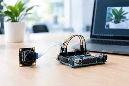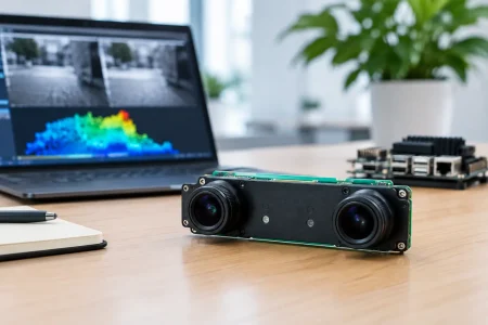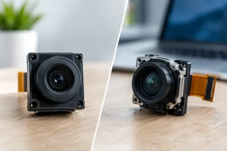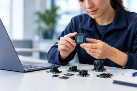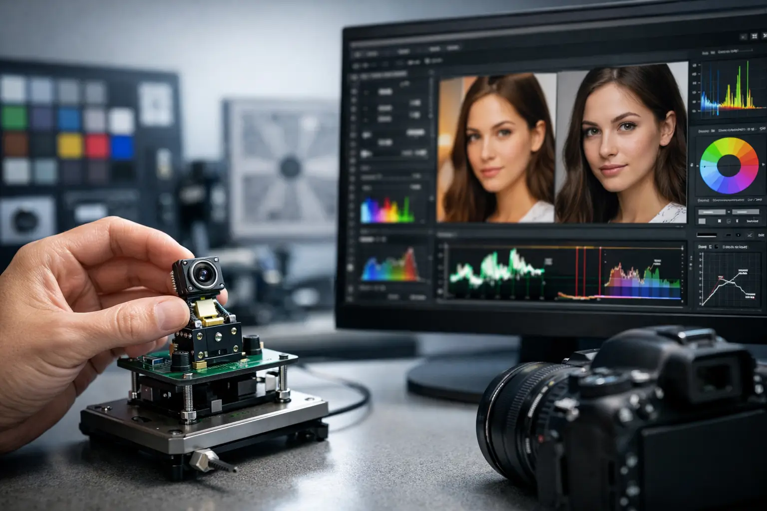
A camera module can meet its resolution and frame-rate targets yet still fail the product experience. Skin tones may shift under warm LEDs, barcodes may blur at the edge of the field, or a robotic arm may lose contrast when moving from sunlight to warehouse lighting. These are image signal tuning problems. Knowing how to improve image signal tuning means treating the sensor, lens, illumination, image signal processor (ISP), and application algorithm as one engineered system.
For embedded product teams, tuning is not a cosmetic final step. It determines whether the image data is stable enough for inspection, recognition, measurement, remote viewing, or clinical documentation. The right process reduces redesign risk before a camera module enters volume production.
Start Image Signal Tuning With the Actual Use Case
A generic “good-looking” image is a poor target. First define what the camera must detect, measure, or communicate and under which lighting conditions. A security camera may prioritize facial detail in mixed lighting. An agricultural camera may need reliable color separation for crop analysis. A medical or industrial endoscope may need controlled white balance, low distortion, and usable detail at close working distances.
Build the tuning target around measurable requirements. These can include minimum illumination, scene dynamic range, acceptable motion blur, color accuracy, signal-to-noise ratio, modulation transfer function, and tolerated frame latency. If the downstream system uses computer vision, validate the output of the algorithm, not only the image on a display. A visually pleasing image with aggressive noise reduction can remove texture that a detection model needs.
Lighting should be characterized early. Test under the expected LED spectrum, daylight, fluorescent sources, and difficult mixed-light scenes. The spectral output of an illumination source directly affects auto white balance and color correction. Changing the LED late in development can invalidate weeks of ISP work.
Match the Sensor, Lens, and ISP Before Adjusting Parameters
Image signal tuning cannot fully compensate for a poorly matched optical stack. A sensor with small pixels may provide high resolution, but it can also require more light and show greater noise in low-light operation. A wide-angle lens expands coverage but can introduce field curvature, distortion, flare, and edge softness. The ISP must be selected and configured with these physical limits in mind.
Start with sensor register settings that establish a controlled baseline: exposure time, analog gain, digital gain, black level, frame rate, pixel format, and high dynamic range mode where applicable. Analog gain is generally preferable to excessive digital gain, but both raise visible noise as illumination falls. Longer exposure improves brightness and signal-to-noise ratio, while increasing motion blur. There is no universal best setting – a conveyor inspection camera and a fixed indoor terminal have different priorities.
Lens shading correction is equally important, particularly for compact camera modules. Vignetting and color shading can vary between the center and corners of the image due to lens design, chief ray angle, and sensor response. Calibrating lens shading correction with controlled flat-field images helps produce even brightness and consistent color across the frame.
The lens must also be focused and mechanically stabilized for its real working distance. Tuning sharpness cannot restore detail that is not captured at the sensor. For fixed-focus modules, verify focus tolerance across the production build, including temperature effects and mechanical stack-up variation.
Establish a Repeatable Reference Scene
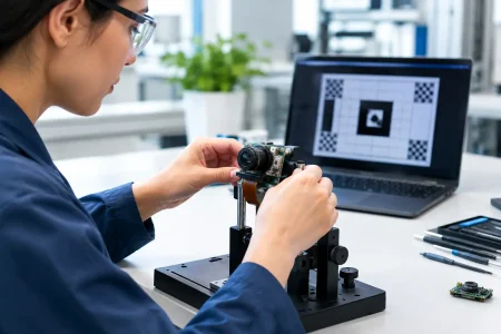
Use calibrated test charts and a controlled light box to establish repeatable results. A practical reference set includes neutral gray patches, color targets, resolution patterns, low-contrast detail, and high-dynamic-range scenes. Capture the same scenes at defined exposure and gain settings so changes in the ISP can be compared objectively.
Automated image-quality measurements are valuable, but engineers should also inspect artifacts that numerical scores can miss. Look for zippering along high-contrast edges, false color, ringing from oversharpening, blotchy chroma noise, banding under LED lighting, and clipped highlights. These defects often become more obvious after video compression or when images are consumed by a machine-vision model.
Tune the ISP in the Right Order
The ISP pipeline contains interdependent controls. Changing denoise can alter perceived sharpness; increasing sharpening can exaggerate noise; auto exposure can affect color and flicker. A disciplined sequence prevents teams from correcting one artifact while creating two more.
Begin with black level and defective-pixel correction. Incorrect black level creates lifted shadows, crushed dark areas, or color casts that contaminate later stages. Then tune demosaicing and noise reduction according to illumination level. Low-light profiles should preserve enough edge information for the application while suppressing objectionable luminance and chroma noise. Daylight profiles can use lower noise reduction and restrained sharpening to retain fine detail.
Next, calibrate white balance and color correction. Auto white balance needs a reliable strategy for the intended scene, especially where there may be no neutral reference area. A color correction matrix should be validated against the actual sensor, lens, IR-cut filter, and illumination combination. A matrix that performs well under daylight may not produce acceptable results under narrow-spectrum LEDs.
Tone mapping, gamma, and dynamic range controls come after color is stable. These settings determine how shadow and highlight detail are distributed for display or analysis. For a human-viewing product, the preferred result may retain bright highlights while gently lifting shadows. For machine inspection, a more linear response may be better because it preserves intensity relationships for thresholding and measurement.
Finally, tune sharpening with restraint. Oversharpening produces halos and false edges, which may look impressive in a quick demonstration but create unstable data and compression artifacts. Apply sharpening by scene condition when the ISP supports it, with lower values at high gain and higher values where the scene is well lit.
Control Flicker, Motion, and High Dynamic Range
Embedded cameras regularly operate under lighting conditions that laboratory tests overlook. LED drivers, fluorescent lamps, displays, and mains-powered lighting can cause visible banding. Configure anti-flicker exposure settings for 50 Hz and 60 Hz environments, then test at the target frame rate. In global deployments, the device may need selectable regional modes or an automatic strategy validated under both conditions.
Motion performance is a trade-off between exposure, noise, and frame rate. Reducing exposure time limits blur but requires more gain or illumination. If the application allows it, improving the illumination design is often more effective than pushing gain and noise reduction. Strobe synchronization can be especially useful for high-speed industrial inspection.
High dynamic range modes can preserve details in bright and dark zones, but they are not free. Multi-exposure HDR can introduce ghosting in moving scenes, increase processing load, or reduce effective frame rate. Test HDR on the actual subject motion, not only on a static chart.
Validate Across Units and Production Conditions
A successful engineering sample does not guarantee a stable production result. Sensor lot variation, lens tolerances, IR-cut filter characteristics, assembly alignment, and thermal conditions can shift image output. Image tuning therefore needs manufacturing-aware validation.
Define acceptance limits for focus, color consistency, shading, dead pixels, noise, and exposure behavior. Production test fixtures should capture the measurements needed to identify module variation before shipment. Where a module requires calibration data, establish a controlled method to write, verify, and trace that data at scale.
This is where an experienced camera-module manufacturing partner adds value. SincereFirst supports custom module development by aligning sensor selection, optical design, ISP configuration, sample validation, and scalable cleanroom production. The goal is not simply to provide a tuned prototype, but to maintain the intended image performance across repeatable builds.
Improve Tuning Through Application-Level Feedback
The final tuning decision should include field feedback. Record difficult scenes from pilot units: reflective packaging, dark cavities, red objects under warm LEDs, moving subjects, backlit entrances, and temperature extremes. These samples reveal the edge cases that test charts cannot fully reproduce.
Create version control for ISP parameter files and document each change with the scene, target metric, and observed trade-off. This discipline prevents untraceable “better image” adjustments from reaching production. It also makes it easier to support future sensor revisions, alternate lenses, or a new illumination design.
The strongest image signal tuning is purposeful rather than aggressive. When the optical stack, ISP settings, illumination, and validation method are designed around the real task, the camera module delivers data that people and machines can trust.