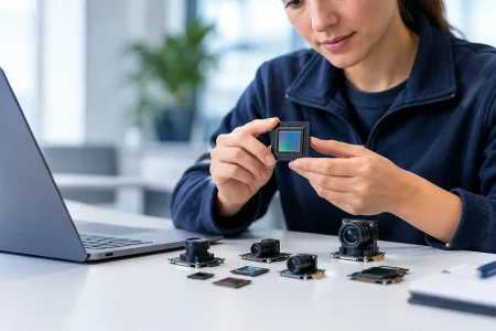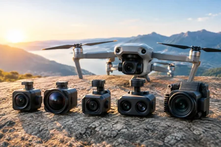
A camera module can meet its resolution target on a bench and still fail the product program. The usual causes are not visible in a datasheet: a marginal MIPI link, an unsuitable lens, poor low-light tuning, thermal drift, or a supplier unable to control changes across production lots. This MIPI sensor module review focuses on the factors embedded teams should evaluate before selecting a module for a commercial device.
For robotics, medical equipment, industrial inspection, security terminals, and smart devices, the correct choice is rarely the sensor with the highest pixel count. It is the module that delivers repeatable image performance inside the available mechanical envelope, power budget, processor capability, and manufacturing schedule.
What a MIPI Camera Module Must Deliver
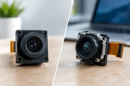
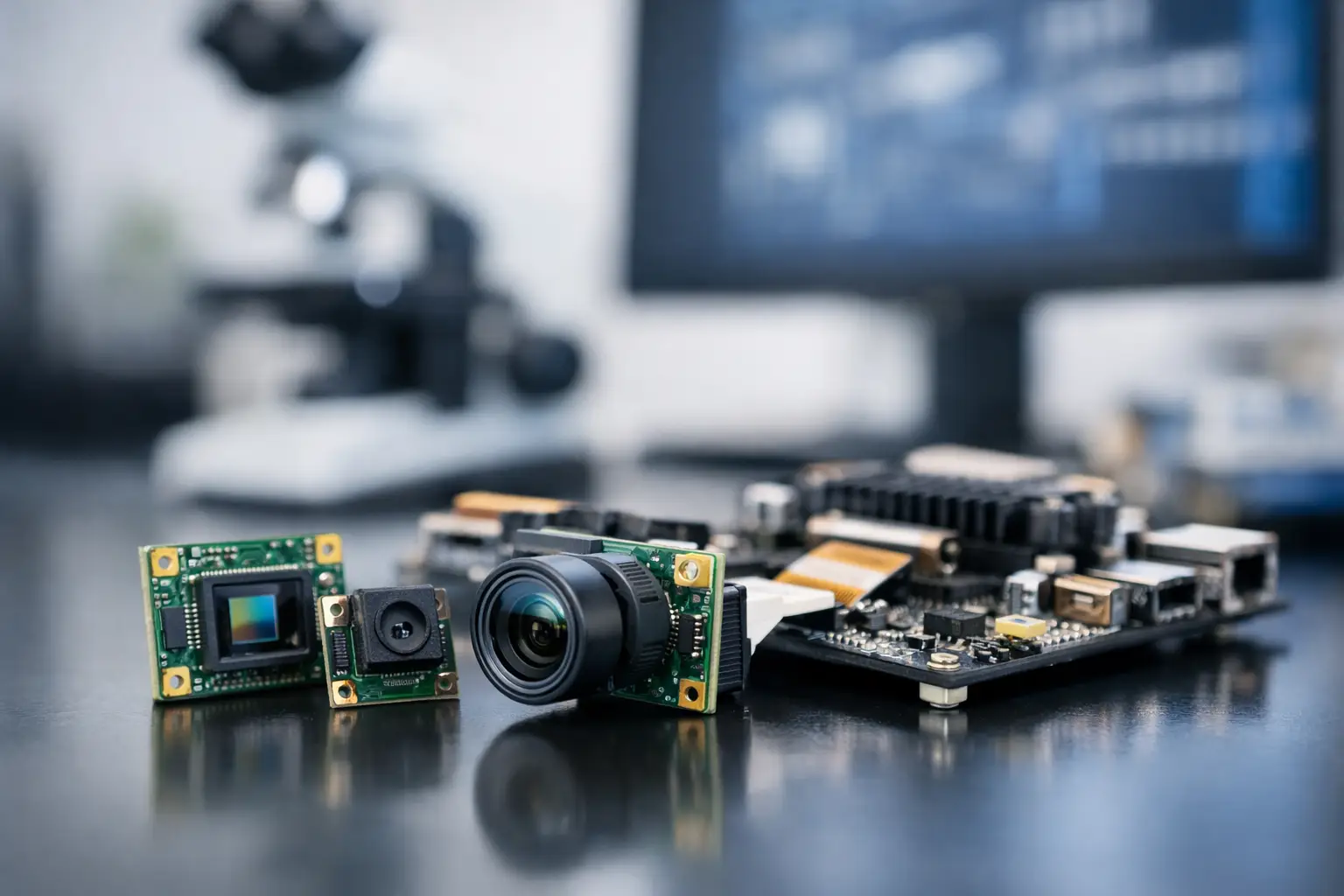
A MIPI camera module combines an image sensor, lens, flexible printed circuit or board, connector, and electrical design around a MIPI CSI-2 output. In many projects, it is the preferred interface because it supports compact hardware, low power consumption, and high-speed image transfer to mobile processors, application processors, and embedded SoCs.
The interface itself is only one part of the decision. A sensor may provide excellent dynamic range, sensitivity, or frame rate, while the complete module can still introduce compromises through lens distortion, assembly tolerance, signal integrity, or unstable image tuning. Procurement teams should therefore evaluate the finished module, not only the sensor model named on the quotation.
A qualified module should match the host platform’s CSI-2 lane configuration, supported lane speed, pixel format, clocking requirements, connector orientation, and driver environment. If one of these items is assumed rather than confirmed, integration time can expand quickly.
MIPI Sensor Module Review: The Technical Criteria That Matter
Sensor performance must match the scene
Start with the actual imaging task. A barcode reader, a surgical visualization device, and an autonomous mobile robot face very different scene conditions. Resolution matters when the system must inspect fine defects or preserve digital zoom detail. In other cases, pixel size, low-light sensitivity, shutter type, and dynamic range have greater influence on usable output.
For moving objects, evaluate whether rolling shutter artifacts are acceptable. A rolling shutter sensor can be cost-effective and deliver high resolution, but it may bend vertical edges or blur fast motion under vibration. Global shutter sensors reduce those effects and are often preferred for machine vision, gesture tracking, industrial automation, and robotics. The trade-off may be lower resolution, different sensitivity characteristics, or a higher module cost.
Ask for representative captures under your real illumination, working distance, motion speed, and target material. A sensor comparison performed under bright, fixed indoor lighting does not predict performance on reflective metal, low-contrast packaging, skin tones, crops in sunlight, or a dim warehouse aisle.
Interface bandwidth is a system calculation
MIPI CSI-2 bandwidth should be calculated before module selection, not after a prototype is built. Resolution, frames per second, bit depth, pixel format, blanking, and lane count all affect the required data rate. A module advertised as 4K or 60 fps is not automatically compatible with the target processor.
RAW output preserves more information for image signal processing and computer vision pipelines, but it places greater demands on the ISP, memory bandwidth, and software stack. YUV output can shorten integration where the host needs display-ready video, but it limits the ability to control demosaicing, noise reduction, color correction, and other image-processing decisions.
Verify the full path: sensor output mode, MIPI lane count, physical layer type, receiver capability, supported formats, Linux or Android driver support, and the processor’s ISP limits. For multi-camera systems, also examine aggregate bandwidth and synchronization requirements. A host that supports two physical camera ports may still lack enough throughput for two high-resolution streams at the intended frame rate.
Lens selection can decide image quality
The lens deserves the same scrutiny as the sensor. Field of view, focal length, aperture, distortion, chief ray angle, depth of field, and near-infrared response must support the application. A wide-angle lens may capture more of a workspace but can create edge distortion that complicates measurement or recognition. A narrow field of view offers more pixels on the target, yet requires tighter aiming and may miss contextual information.
Fixed-focus modules work well when object distance is controlled, such as document scanning, fixed inspection stations, and access-control terminals. Auto-focus can be useful in consumer-style devices or variable-distance applications, but it adds mechanical behavior, power demands, control complexity, and test requirements. For highly compact products, an appropriately specified fixed-focus lens is often the more dependable production choice.
Check corner sharpness rather than judging only the image center. Also request distortion data and module-to-module focus tolerance. These details are particularly relevant for measurement, stitching, calibration, and AI models trained on production images.
Image tuning should be application-specific
Image signal processing determines how the raw sensor data becomes a usable image. Exposure control, white balance, noise reduction, sharpening, color correction, high dynamic range behavior, and flicker handling can materially affect a product’s output.
Generic tuning may be acceptable for an early proof of concept. It is rarely the final answer for an embedded product with controlled performance targets. Medical visualization may need faithful color and texture. Security systems may prioritize low-light detail and highlight control. Agricultural systems may require consistent color response across outdoor light conditions. Industrial readers may value edge contrast over visually pleasing images.
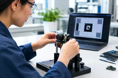
Review sample images and video with the intended host processor whenever possible. The same module can look different on separate platforms because the ISP pipeline, drivers, and tuning files differ. Establish objective acceptance criteria, such as minimum illumination performance, color error range, modulation transfer performance, frame stability, or detection accuracy for the final algorithm.
Mechanical, Thermal, and Reliability Checks
Compact MIPI modules are sensitive assemblies. The FPC length and bend condition, connector retention, grounding, shielding, mounting surface, and lens-holder clearance can all affect final performance. A module that fits in CAD may be difficult to assemble repeatedly if the connector lacks access or the FPC bend radius is too tight.
Thermal conditions require early attention. Sensor temperature can change noise behavior, dark current, frame stability, and image consistency. Heat from the processor, display, battery, LEDs, or enclosure may reach the module in a small device. Evaluate images after thermal soak, not only at startup. If the product operates outdoors or near machinery, define the temperature range and test the full camera path within it.
Reliability review should cover vibration, drop exposure where applicable, humidity, electrostatic discharge protection, connector mating cycles, and contamination control. For endoscope and medical imaging designs, waterproofing, sterilization compatibility, biocompatibility requirements, and extremely small mechanical tolerances may become central design constraints rather than secondary checks.
Evaluate the Supplier, Not Just the Sample
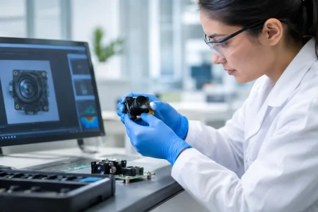
A successful sample proves that a design is possible. It does not prove that thousands of units will perform consistently. Production readiness depends on incoming inspection, cleanroom assembly, optical alignment control, image testing, traceability, engineering change management, and the supplier’s ability to maintain component availability.
During supplier qualification, ask how the module is tested and what records can be provided by lot. Clarify whether focus, shading, dead pixels, MIPI output, and cosmetic conditions are inspected. Confirm how lens or sensor substitutions are controlled, how long-term supply risks are communicated, and whether the supplier can support custom FPC layouts, connectors, lens options, and firmware or tuning requirements.
For teams moving quickly from prototype to commercialization, engineering responsiveness matters as much as catalog breadth. SincereFirst supports standard and custom camera module programs with optical, electronic, and manufacturing capability built around compact embedded imaging. The practical value is a shorter path from interface definition and sample validation to scalable production control.
A Better Qualification Process
Treat camera selection as a gated engineering process. First, define the scene, working distance, target size, illumination, motion, and output requirements. Next, confirm host compatibility at the electrical and software level. Then test complete modules in the intended enclosure, with the intended lens and processor, across the expected environmental range.
Before releasing production, run pilot units through mechanical assembly, thermal operation, image-quality inspection, and application-level validation. This process exposes the issues that datasheets miss: connector access problems, bandwidth limits, exposure instability, lens variation, and algorithm failures at the edge of the field.
The best module is not necessarily the most expensive, smallest, or highest-resolution option. It is the one whose sensor, optics, MIPI interface, image tuning, and manufacturing controls are aligned with the product you intend to ship. That alignment turns a camera module from a purchased component into an intelligent eye your system can depend on.