A camera module that fits the enclosure but misses a moving label, fails under factory lighting, or overloads the host processor is not a usable machine vision solution. That is why learning how to customize machine vision modules starts with the full imaging task, not a sensor catalog. For OEMs and system integrators, the goal is to turn an application requirement into a module that can be repeatedly built, calibrated, tested, and supplied at production volume.
How to Customize Machine Vision Modules From Application Requirements
Begin with the decision the camera must support. A robotic arm may need to locate parts within millimeters. A barcode reader may need to capture fast-moving codes under mixed lighting. A medical device may prioritize color accuracy, low noise, compact diameter, and controlled illumination. These are different imaging problems, even if each product uses a small embedded camera.
Define the scene before defining the module. Document the working distance, field of view, object size, object speed, lighting conditions, required detection accuracy, and acceptable image latency. Also identify whether image processing occurs on the host, at the edge, or in a dedicated vision processor. This prevents a common mistake: selecting a high-resolution sensor when the real constraint is motion blur, depth of field, or host bandwidth.
Set measurable image targets
Specifications should translate into pass or fail criteria. Instead of requesting “clear images,” specify the smallest feature that must be resolved, the acceptable distortion level, the required frame rate, and the signal-to-noise performance under the lowest expected illumination. For color-sensitive applications, define color temperature ranges and whether automatic white balance is allowed.
For measurement or inspection work, consider pixel scale. If a defect must be detected at 0.2 mm and each pixel represents 0.25 mm in the object plane, the system cannot reliably see it. The lens, sensor resolution, working distance, and field of view must be calculated together.
Define mechanical and environmental limits early
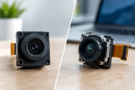
Module dimensions, board outline, connector position, cable routing, mounting holes, and lens height should be fixed as early as possible. In compact devices, a few millimeters can decide whether a design is manufacturable. FPC length and bend direction also matter, especially in handheld equipment, endoscopic devices, robotics joints, and enclosed industrial assemblies.
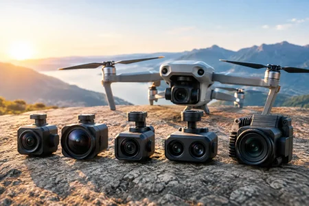
Environmental requirements affect component selection and validation. State operating temperature, vibration exposure, humidity, dust, electromagnetic interference, and expected product lifetime. A module intended for a clean indoor kiosk does not need the same design decisions as one installed near industrial machinery or outdoors in changing light.
Customize the Sensor, Optics, and Illumination as One System
The sensor is central, but it is not the whole camera. A well-matched optical stack and illumination strategy often improve usable results more than increasing megapixels.
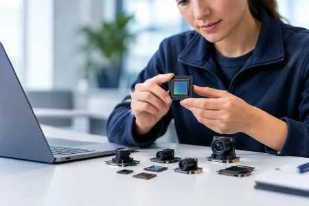
Choose the sensor for the imaging task
Resolution determines the available detail, but sensor format, pixel size, shutter type, sensitivity, dynamic range, and frame rate determine whether that detail can be captured in real conditions. Global shutter sensors are often the better choice for moving objects, conveyor inspection, and robot guidance because they reduce geometric distortion. Rolling shutter sensors can be cost-effective for static scenes or controlled motion, but they require evaluation when vibration or high speed is present.
Larger pixels can improve low-light performance, while a higher-resolution sensor can support digital cropping or wider fields of view. These benefits involve trade-offs in module size, data rate, processor load, power consumption, and cost. The right choice depends on the complete system budget, not on a single headline specification.
Match the lens to working distance and tolerance
Lens selection should be based on focal length, field of view, aperture, distortion, resolution capability, and depth of field. A wide-angle lens can cover more area but may introduce distortion that requires calibration or software correction. A narrow field of view may deliver better pixel density on a target but makes alignment more sensitive.
Focus method also matters. Fixed-focus modules are appropriate when the working distance is controlled and offer lower complexity. Autofocus adds flexibility for variable-distance use cases but introduces mechanical and control considerations. For inspection equipment, a manually focused and locked lens may offer the best balance of repeatability and cost.
Illumination should be specified alongside the module. Ring lights, side lights, coaxial lights, infrared LEDs, and visible LEDs create different contrast conditions. If the product requires integrated LEDs, define wavelength, brightness, thermal limits, control method, and the optical path needed to avoid reflections or hotspots.
Select the Interface and Electronics for the Host Platform
The interface must match both the host hardware and the required image throughput. MIPI CSI-2 is common in compact embedded systems where low power and direct processor connection are priorities. USB 2.0 and USB 3.0 modules are practical for PCs, industrial controllers, and rapid integration. DVP remains relevant for certain legacy or lower-complexity embedded designs, while UVC support can simplify driver compatibility for standard USB hosts.
Do not select an interface only because it is familiar. Calculate the actual throughput from resolution, frame rate, bit depth, and image format. A high-resolution stream at 60 fps may exceed the capacity of the selected bus or create unacceptable processor latency. Compression can reduce bandwidth, but it may also affect image quality and add processing delay.
Customization may include a dedicated PCB layout, connector type, FPC arrangement, clock configuration, voltage requirements, LED driver circuitry, EEPROM settings, and shielding provisions. Firmware parameters such as exposure, gain, image orientation, frame timing, defect-pixel correction, and image signal processor tuning should be controlled and documented. A module is easier to qualify when its default behavior is predictable across every production lot.
Build Prototypes Around Real Integration Tests
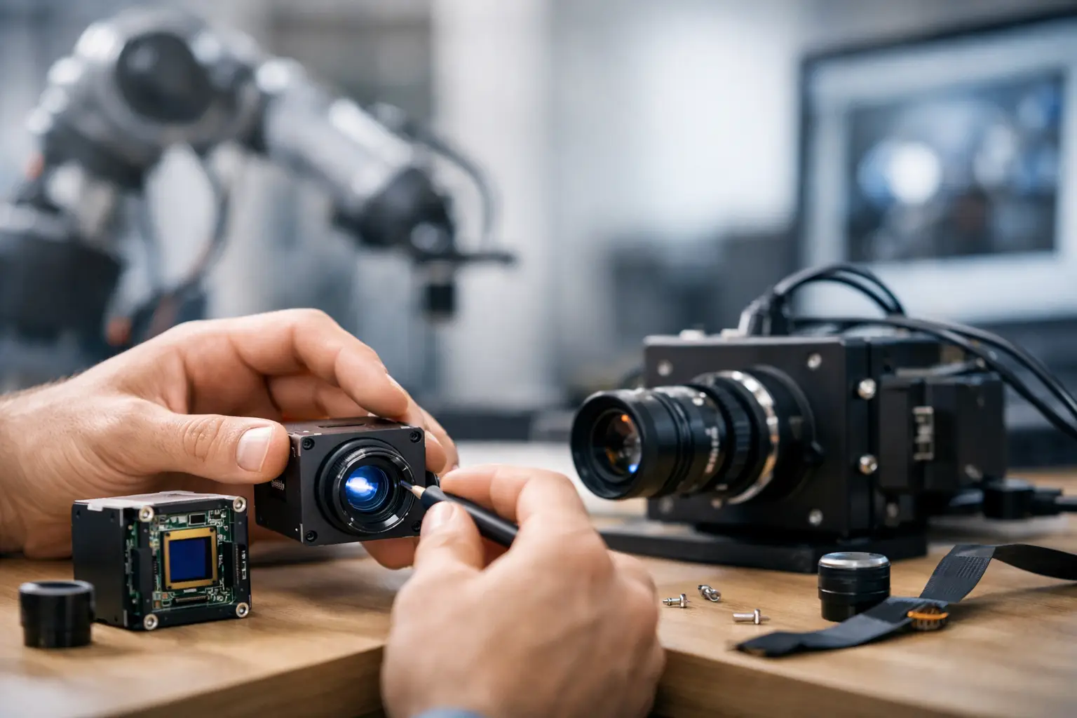
A prototype proves more than whether the camera turns on. It should be evaluated inside the intended enclosure, with the intended cable, processor, lighting, and software pipeline. Test representative production scenes rather than a single well-lit bench target.
Review image quality across operating conditions: minimum and maximum working distance, low and high light, motion, temperature range, and expected vibration. Check for lens shading, flare, focus shift, color variation, dropped frames, electrical noise, and thermal effects. If the device uses computer vision algorithms, measure detection accuracy and processing latency with the final image settings.
This stage is where an experienced module manufacturer adds practical value. SincereFirst combines custom optical, PCB, interface, and assembly development with manufacturing-oriented evaluation, helping teams avoid designing a prototype that cannot be consistently reproduced at scale.
Plan Production Controls Before Design Freeze
A custom machine vision module needs clear production controls, not only approved engineering samples. Agree on the critical specifications that will be inspected in mass production. Depending on the application, this can include resolution, focus position, field of view, distortion, sensor defects, color response, LED output, current consumption, and interface stability.
Define the test method as carefully as the specification. For example, a focus requirement is incomplete without a target distance, chart type, lighting condition, and acceptance threshold. The same applies to color, frame rate, and image noise. Objective test standards reduce disputes and help maintain consistency when volumes increase.
Supply planning belongs here as well. Confirm approved sensor and lens alternatives, component lifecycle expectations, packaging requirements, traceability needs, and change-notification procedures. Single-source components may be appropriate for a specialized design, but they create supply risk that should be understood before launch. In high-volume programs, an approved second source or a qualified redesign path can protect continuity.
Avoid Costly Customization Mistakes
The fastest way to extend development time is to treat mechanical, optical, electronic, and software decisions as separate projects. A connector move can force a PCB change. A sensor change can alter lens selection and bandwidth. An enclosure window can introduce reflection that affects the vision algorithm. Cross-functional review prevents these late-stage surprises.
Avoid over-specifying features that do not improve the end result. Higher resolution, autofocus, premium optics, or USB 3.0 may be justified, but only when they support a measurable application need. At the same time, do not reduce cost by accepting an untested lens, marginal bandwidth, or weak production criteria. Those decisions often reappear as field failures, inconsistent quality, or costly rework.
A well-customized module is not simply smaller or higher resolution. It is a controlled imaging subsystem designed around the object, the environment, the host platform, and the realities of production. Start with the image decision your product must make, then let that requirement drive every engineering choice through validation and volume manufacturing.