A camera module that performs well on a lab bench can still fail the product program. The usual causes are not sensor resolution alone. They are mismatched optics, an unstable MIPI link, heat inside a sealed enclosure, an image pipeline that was never tuned for the actual scene, or a design that cannot be manufactured consistently. This custom camera module development guide is built for OEM teams that need to move from an imaging requirement to a production-ready component without adding avoidable redesign cycles.
Start With the Imaging Job, Not the Resolution
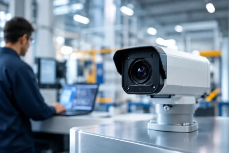
The most productive camera specification begins with the scene the device must capture. A warehouse robot identifying barcodes at speed needs different exposure behavior, field of view, and motion performance than a medical handheld device examining close-range tissue. A security terminal operating across bright sun and low indoor light has different dynamic range demands than an agricultural camera viewing crops in daylight.
Define the working distance, required field of view, target feature size, motion speed, illumination range, and acceptable capture latency. These inputs establish whether the design needs a wide-angle lens, a telephoto optical path, fixed focus, autofocus, global shutter, rolling shutter, visible light, near-infrared sensitivity, or integrated LEDs.
Resolution should follow the task. If an object must occupy enough pixels for recognition or measurement, calculate the needed pixels across that object at the farthest relevant distance. Specifying a high-resolution sensor without considering lens sharpness, processor bandwidth, storage, and thermal load can add cost without delivering usable detail.
Define Pass and Fail Conditions Early
Product teams should convert broad expectations such as “clear image” into measurable criteria. Examples include minimum line pairs per millimeter at the target plane, barcode read rate, color error under a defined illuminant, low-light signal-to-noise ratio, maximum dead-pixel allowance, or end-to-end frame latency.
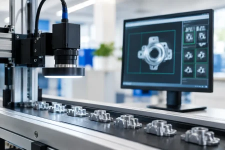
For regulated medical products, documentation, traceability, cleaning constraints, and optical consistency may carry as much weight as image quality. For industrial automation, a stable frame rate, repeatable exposure, vibration resistance, and long-term supply may be the deciding factors. The specification must reflect the commercial environment, not only the ideal image.
Custom Camera Module Development Guide: Select the Right Architecture
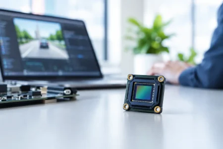
Once the imaging task is clear, select an architecture that fits the host system and mechanical envelope. The camera module includes more than a sensor. It is an integrated combination of image sensor, lens, FPC or PCB, connector, power design, clocking, interface, firmware support, and mechanical structure.
MIPI CSI-2 is often the preferred choice for compact embedded products using mobile-class processors because it supports high data rates in a small footprint. It requires disciplined signal-integrity design and host-side driver support. USB UVC modules are generally easier to integrate with PCs and many embedded platforms because standard video-class support reduces driver work, although cable length, bandwidth sharing, and power delivery still require validation. DVP can remain practical for legacy or lower-bandwidth systems where processor compatibility is already established.
The interface choice affects sensor options, cable routing, connector selection, and production test strategy. It should not be treated as a final packaging decision. Confirm the host processor’s supported lane count, input clock requirements, pixel formats, virtual channels, and maximum throughput before locking the module design.
Sensor Selection Is a Trade-Off Exercise
Sensor size, pixel size, frame rate, shutter type, sensitivity, and dynamic range must work together. Larger pixels can improve low-light performance but may increase module dimensions or cost. A global shutter reduces motion artifacts in robotics, scanning, and fast-moving industrial scenes, yet it may offer different resolution and low-light trade-offs from a comparable rolling-shutter sensor.
Pixel format also matters. RAW output preserves flexibility for image signal processor tuning and computer vision pipelines, but it demands capable host processing. YUV output can shorten integration for display or USB video applications, although the module or sensor’s processing behavior may limit later image adjustments.
Supply continuity should be evaluated at the same time. A component that is technically attractive but approaching end of life can create a second qualification program before the product reaches volume. An experienced module manufacturer can propose sensor alternatives, but the OEM should decide which image-performance differences are acceptable before procurement pressure appears.
Match Optics to the Real Mechanical Envelope
Lens selection determines whether sensor performance reaches the application. Field of view, focal length, f-number, distortion, chief ray angle, depth of field, and focus strategy all need to be assessed together. A wide-angle lens may cover the desired scene but introduce distortion that complicates metrology or edge recognition. A faster lens can help in low light but may reduce depth of field, making fixed-focus performance less forgiving.
For fixed-focus modules, set the focus position based on the primary operating distance and allowed depth of field. Do not assume infinity focus is appropriate for a device that mainly captures objects 150 mm away. For autofocus designs, verify focus time, repeatability, current consumption, and operation after shock, vibration, and repeated temperature changes.
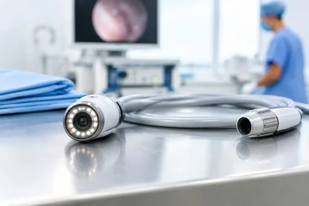
Miniaturized endoscope and medical imaging modules add further constraints. Diameter, distal-end length, cable flexibility, LED placement, waterproofing, and heat control can directly affect optical design. In these applications, a custom optical path is often necessary because a standard lens barrel will not fit the device geometry.
Design the Electrical and Mechanical Integration Together
Many camera failures originate at the boundary between module and product. FPC bend radius, connector orientation, cable length, grounding strategy, shield placement, and mounting datum positions should be reviewed during the first mechanical layout. A compact module with a difficult cable exit can create assembly damage or signal problems at scale.
MIPI designs deserve particular attention. Differential-pair impedance, lane-length matching, controlled routing, return paths, and EMI protection must be maintained through the module, flex cable, and host board. A prototype may operate with a short engineering cable but fail when the final product introduces a longer flex, a metal housing, or a nearby radio.
Thermal behavior also changes images. Sensor temperature can increase noise, while lens-holder expansion can shift focus. Test the camera inside the final enclosure at full processor load, with the expected display, wireless functions, and illumination active. The best time to discover thermal image drift is before tooling is released.
Treat Image Tuning as Product Engineering
A sensor datasheet cannot predict the image quality your users will see. Image tuning aligns exposure, gain, white balance, noise reduction, sharpening, lens shading correction, and color processing with the product’s lighting conditions and display or vision algorithm.
For machine vision, aggressive noise reduction or sharpening can alter edges and reduce measurement reliability. For a consumer-facing display, a more pleasing image may be the priority. Neither approach is universally correct. The tuning target depends on whether the camera supports a human operator, an AI model, a measurement system, or a recorded evidence stream.
Provide representative samples to the development team: target objects, printed materials, skin tones when relevant, reflective surfaces, actual LED spectra, and images from difficult scenes. Testing only a standard color chart will not expose the glare, flicker, shadows, or motion blur that matter in the finished device.
Build a Validation Plan Before Tooling
Validation should cover optical, electrical, mechanical, and manufacturing performance. Create a test plan that names the method, equipment, sample size, pass criteria, and response to a failure. This prevents different teams from using different definitions of acceptable quality.
A complete program commonly evaluates image uniformity, MTF or sharpness, distortion, color, dark noise, defective pixels, frame stability, interface errors, ESD behavior, vibration, drop or shock, high and low temperature operation, humidity, and cable or connector durability. The exact scope depends on the application. An indoor kiosk and a vehicle-mounted industrial camera should not be qualified to the same environmental profile.
Manufacturing test needs equal attention. A production line must verify focus, sensor output, interface communication, current consumption, and cosmetic condition quickly enough to support volume. If each module requires a manual visual judgment, yield and consistency will suffer. Calibration fixtures, golden samples, image-analysis software, and traceable test records make the transition from engineering samples to mass production far more predictable.
Choose a Supplier That Can Support the Full Lifecycle
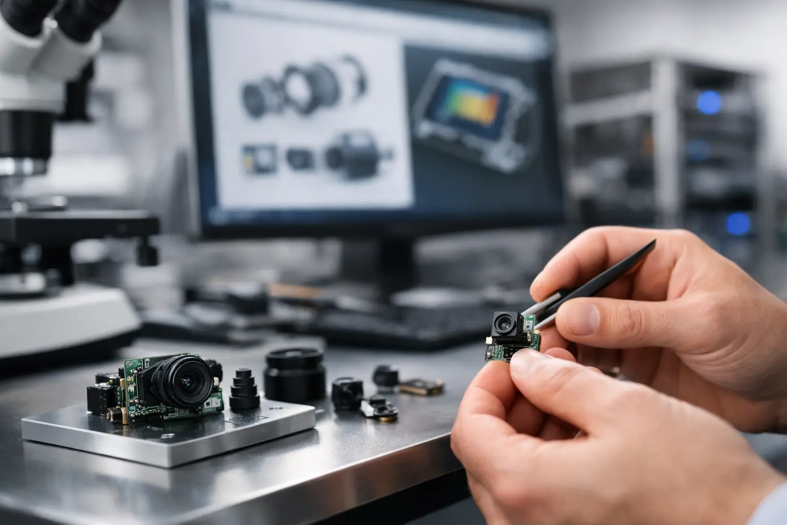
The right partner can provide standard modules for early feasibility work while developing a custom configuration for the final product. Assess engineering response speed, sensor and lens sourcing capability, cleanroom assembly control, active alignment or focus capability, reliability testing, quality documentation, and capacity planning. Ask how design changes are controlled once samples have been approved.
SincereFirst supports this process through custom embedded camera module development, optical integration, rapid samples, and scaled manufacturing for industrial, medical, robotics, security, and smart-device programs. The practical value is not simply access to more module options. It is reducing the gap between a promising prototype and a camera design that can be repeatedly built, tested, and supplied.
A camera module should earn approval in the conditions where the product will work, not only under controlled lab lighting. Bring the supplier, host-platform team, mechanical engineers, and quality team into that evaluation early. Clear requirements at the beginning create faster decisions later, protect the production schedule, and give the finished device the intelligent eyes it was designed to have.