A robot arm can stop perfectly at the end of its stroke and still appear bent in the image. A barcode may be readable in a static test but fail on a fast conveyor. These are common reasons engineers ask how to optimize rolling shutter before approving a camera module for production. The issue is not simply image quality. It is the interaction between sensor readout, motion, illumination, optics, interface bandwidth, and the real timing of the application.
Rolling shutter sensors capture an image line by line rather than exposing every pixel at the same instant. This architecture supports compact camera modules, low power operation, high resolution, and cost-effective supply. It is well suited to many embedded and industrial systems. But when the object, camera, or light source changes during frame capture, each row represents a slightly different moment in time. The result can be skew, wobble, partial exposure differences, or motion blur.
How to Optimize Rolling Shutter for the Application
The first engineering decision is to quantify motion rather than treating rolling-shutter distortion as a generic camera problem. A camera that performs well in a handheld terminal may be unsuitable for a high-speed pick-and-place station. Likewise, a rolling shutter module can be an efficient choice for a stationary medical device or access-control terminal when its timing is matched to the scene.
Start with the maximum relative motion between the camera and the feature that matters. For a conveyor application, this is usually belt speed. For a mobile robot, it may include vehicle speed, vibration, turning rate, and the distance to the target. For a rotating part, angular velocity and radial position both affect visible displacement.
Then examine the sensor timing specifications. The most relevant values are frame period, exposure time, line time, and full-frame readout time. Exposure time controls how much motion blur accumulates within each line. Readout time controls how much the scene can change from the first row to the last row.
A useful practical model is:
Image displacement = object speed × exposure time × image scale
Image scale converts real-world movement into pixels. If a feature moves several pixels during exposure, it will blur even if rolling-shutter skew is minor. For distortion across the frame, compare object movement during total readout with the acceptable positional error in pixels.
This distinction matters. Reducing exposure may produce a sharper image, but it does not necessarily eliminate geometric skew if the sensor still reads the frame slowly. A production-ready solution must manage both effects.
Set Exposure for Motion, Not for Maximum Brightness
Long exposure is often the first source of failure. Automatic exposure can select a duration that creates a bright image under weak ambient light, while sacrificing edge definition and measurement accuracy. For machine vision, brightness is useful only when the required feature remains sharp enough for the algorithm.
Set a maximum exposure based on the fastest expected motion and the smallest feature the system must resolve. If a vision algorithm needs an edge location within one or two pixels, design the exposure so motion during that interval stays below that limit. In many industrial systems, this means using a short, fixed exposure rather than allowing auto exposure to react freely to changing backgrounds.
The trade-off is clear: shorter exposure reduces collected light and can increase gain, noise, or both. The correct response is usually not to accept excessive gain. It is to provide controlled illumination, select an appropriate lens aperture, and choose a sensor with suitable sensitivity for the wavelength and operating environment.
Use Controlled, Pulsed Illumination
A bright LED strobe can freeze motion far more effectively than continuous lighting at the same average power. When synchronized to the camera exposure, a short pulse supplies high peak illumination only when the sensor is capturing the image. This allows short exposures without forcing excessive sensor gain.
For repeatable inspection, strobe timing should be tied to a hardware trigger rather than software timing. The camera receives a trigger from the PLC, encoder, or motion controller; the camera starts exposure; and the light pulse occurs within the valid exposure window. This approach reduces variation caused by operating-system latency, network traffic, and inconsistent frame delivery.
Lighting selection also requires care. Low-quality LED drivers can flicker at mains-related frequencies or through pulse-width modulation. With rolling shutter, different rows may capture different phases of the light cycle, producing horizontal brightness bands. Use flicker-free constant-current illumination, synchronize the light source, or select exposure and frame timing that are compatible with the illumination frequency.
Reduce Readout Time and Control Frame Timing
Exposure control addresses blur. Readout control addresses the time difference between top and bottom image rows. Select a sensor mode that minimizes readout time while maintaining enough resolution and signal quality for the task.
Many sensors offer frame-rate modes, region-of-interest settings, binning, or subsampling options. A smaller vertical region of interest can substantially reduce the number of rows being read. For example, if an application only needs the central area where parts pass through the field of view, capturing the full sensor height can add distortion with no inspection benefit.
Increasing frame rate may also reduce frame readout time, depending on sensor architecture and mode. However, higher frame rate can raise interface bandwidth, processing load, power consumption, and thermal output. It can also reduce available exposure time. Confirm the complete pipeline: sensor output, MIPI CSI-2 or USB throughput, ISP performance, memory bandwidth, and host processing capacity.
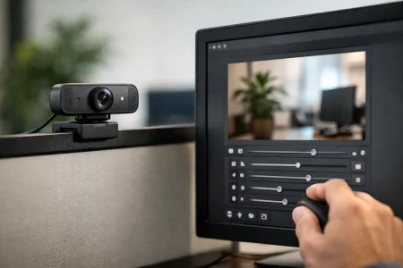
A camera module should also be configured for deterministic timing. Disable uncontrolled auto-exposure and auto-white-balance behavior when color consistency and geometric repeatability are critical. Use external trigger, frame sync, or a stable internal timing source where the application requires exact image-to-motion correlation.
Synchronize the Camera With Motion
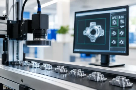
In conveyor inspection, an encoder is often more valuable than a higher-resolution sensor. Encoder-based triggering captures images at defined travel increments, ensuring that each frame represents a known position on the belt. This improves inspection consistency and simplifies downstream measurement.
For moving cameras, synchronize image capture with motion states when possible. A robot can capture after settling at a waypoint, a drone can select frames using inertial data, and an automated guided vehicle can reduce exposure during high-vibration movement. Mechanical stabilization does not replace timing control, but it reduces the motion the camera must tolerate.
If the target motion is periodic, such as a rotating fan, motor shaft, or packaging wheel, phase-locking the camera trigger to the motion cycle can produce stable images. The objective is not always to stop motion visually. Sometimes the system only needs every image to represent the same phase, allowing software to inspect a repeatable view.
Optimize Optics and Module Integration
Lens choice influences rolling-shutter performance because magnification determines how quickly real movement becomes pixel movement. A narrow field of view magnifies the target and may make small vibrations appear severe. A wider field of view reduces pixel displacement but can make the feature too small for reliable detection. The correct lens balances measurement resolution against motion tolerance.
Depth of field matters as well. Closing the aperture can improve focus tolerance, but it reduces light and may force a longer exposure. In high-speed imaging, it is often preferable to increase controlled illumination instead of closing the aperture so far that exposure must rise.
Camera mounting deserves the same attention as sensor selection. Flexible brackets, long unsupported cables, unstable enclosures, and nearby motors can introduce vibration that becomes visible as wobble or rolling-shutter distortion. Use a rigid mounting path, strain relief, vibration isolation where appropriate, and repeatable optical alignment. For compact embedded products, validate the camera module after final enclosure assembly, not only on an open engineering bench.
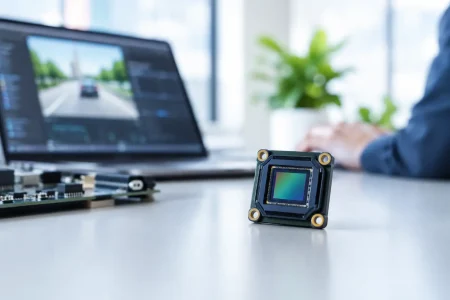
Module-level integration also affects image timing. MIPI camera modules require correct lane configuration, clocking, and receiver tuning. USB camera modules need sufficient bus bandwidth and stable host-side handling. Frame drops, buffering delays, or ISP changes may not create rolling-shutter distortion directly, but they can break synchronization and make the system appear inconsistent in the field.
For custom camera development, define the sensor mode, lens, illumination wavelength, trigger method, cable length, enclosure constraints, and host interface early. SincereFirst supports this type of module-level evaluation because rolling-shutter performance is determined by the complete imaging chain, not by a sensor data sheet alone.
Know When Global Shutter Is the Better Choice
Optimization has limits. If the application requires accurate imaging of fast, unpredictable motion, a global shutter sensor may be the more reliable engineering decision. Global shutter exposes all pixels at nearly the same time, which largely removes line-to-line geometric distortion.
This is especially relevant for high-speed robotics, fast conveyor metrology, aerial imaging, sports tracking, vibration analysis, and motion-critical measurement. The trade-offs can include sensor cost, resolution availability, power, sensitivity, and module selection. A global shutter is not automatically superior for every product. In static or moderately moving scenes, a well-controlled rolling shutter design can deliver excellent image quality with a more compact and economical architecture.
The best specification is therefore not “rolling shutter” or “global shutter” in isolation. It is a measurable requirement: maximum target speed, allowed blur in pixels, allowed geometric error, lighting conditions, trigger repeatability, and required production throughput. Test against those limits using real motion, final optics, final illumination, and the intended host platform. That validation turns rolling-shutter control from a lab adjustment into a dependable imaging design choice.