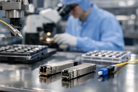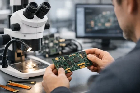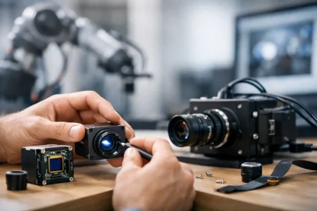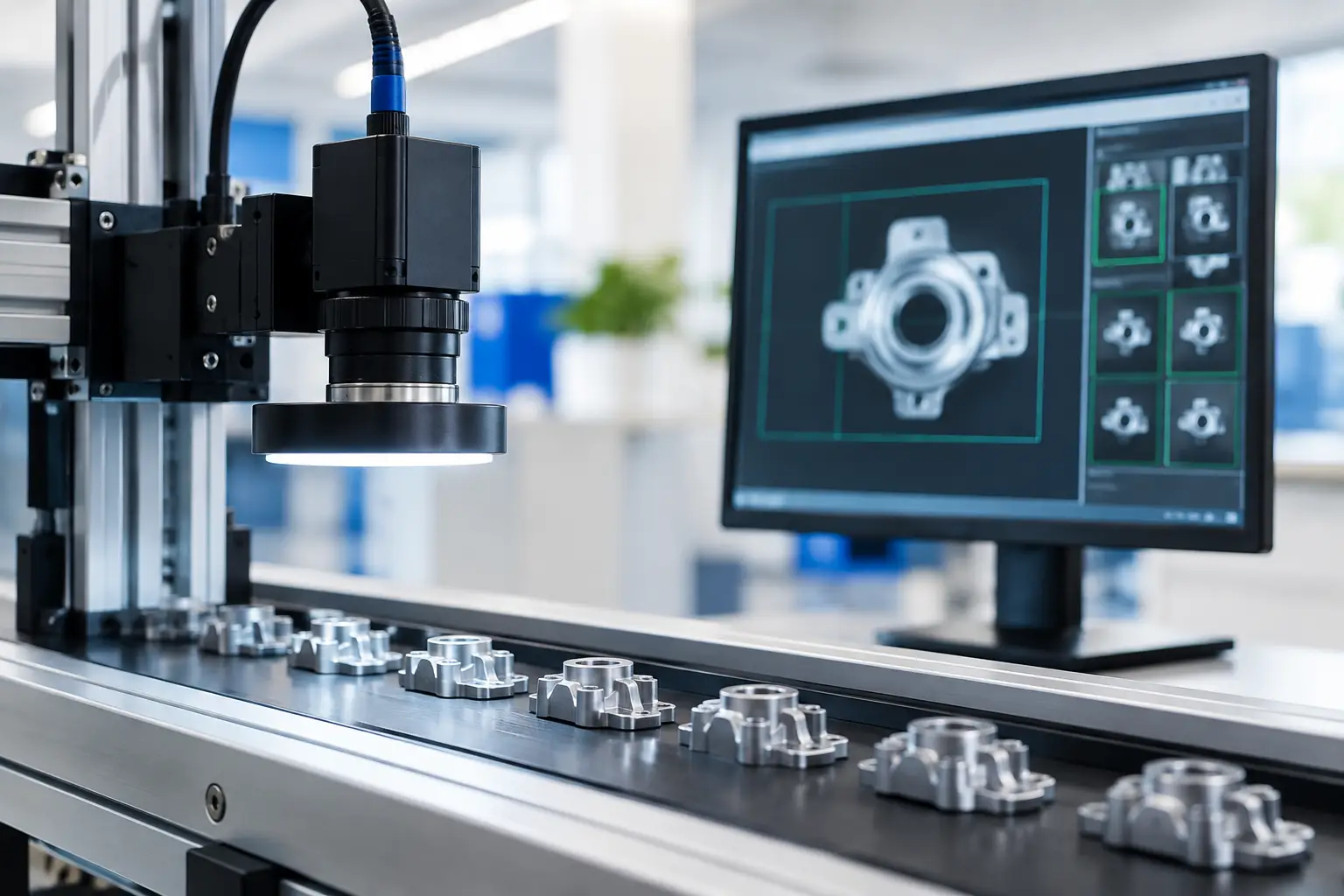
A camera interface can become the limiting factor long before the sensor reaches its potential. If an inspection system needs high-resolution images at meaningful frame rates, USB2.0 may not carry enough data, while GigE Vision may add network design and latency considerations the machine does not need. Knowing when to use USB3 Vision helps engineering teams select an interface that matches the image pipeline, installation constraints, and production plan.
USB3 Vision is an industrial camera interface standard built on USB 3.x transport and the GenICam framework. It is designed for machine vision applications that need high data throughput, direct host connection, standardized camera control, and relatively simple integration. It is not automatically the best choice for every USB camera project. The right decision depends on bandwidth, cable length, synchronization requirements, host architecture, and the cost of scaling the system.
When to Use USB3 Vision for High-Data Imaging
USB3 Vision is a strong fit when a camera must transfer uncompressed image data faster than USB2.0 can reliably support. A USB 3.0 connection has a nominal signaling rate of 5 Gbps, although actual available image bandwidth is lower after protocol overhead and host-controller behavior are considered. That capacity makes the interface practical for many high-resolution, high-frame-rate industrial imaging tasks.
For example, a monochrome 5 MP sensor operating at 30 fps produces roughly 150 MB/s before overhead when sending 8-bit pixels. A USB2.0 camera is unlikely to sustain that stream without reducing frame rate, resolution, bit depth, or compression. USB3 Vision can handle this type of workload with far more margin when the camera, cable, and host are designed correctly.
It is particularly appropriate for automated optical inspection, electronics assembly verification, laboratory instruments, document scanning, robotics guidance, and quality-control stations. These applications often need detailed imagery, low transfer latency, and a camera installed near an embedded computer or industrial PC.
The interface is also attractive when the system architecture is one camera per nearby host port. USB connections are familiar to embedded developers, and the direct point-to-point topology can reduce network configuration work compared with Ethernet-based systems. For a compact inspection cell, a USB3 Vision camera module can offer a practical balance between throughput and integration effort.
The Performance Case: Resolution, Frame Rate, and Pixel Format
The first decision should be based on image payload, not the connector label. Calculate the approximate data rate by multiplying image width, image height, bits per pixel, and frames per second. Then add enough margin for transport overhead, exposure variation, software buffering, and future sensor changes.
USB3 Vision is often selected when one or more of these conditions apply:
- The application needs multi-megapixel imaging at moderate to high frame rates.
- The camera outputs RAW, Bayer, monochrome, or other uncompressed formats needed for reliable machine vision processing.
- The system requires low-latency transfer from camera to a local processor.
- The camera must support industrial controls such as hardware triggering, exposure settings, gain control, region of interest, and GenICam-compatible software access.
A lower-resolution camera running at a modest frame rate may not need this bandwidth. In those cases, USB2.0 can be more cost-effective and easier to route in a compact product. Conversely, a very high-speed system with multiple cameras may exceed what a single USB host controller can support, even if each individual camera appears compatible on paper.
Pixel format matters as much as resolution. A 12-bit or 16-bit image stream consumes significantly more bandwidth than 8-bit output. Color processing can also change the calculation. Sending RAW Bayer data may preserve maximum sensor information and reduce camera-side processing, while RGB output can triple the payload per pixel. The optimal choice depends on where image processing occurs and what level of image fidelity the application requires.
USB3 Vision Is Not the Same as Any USB3 Camera
A USB camera with a USB 3.0 connector is not necessarily a USB3 Vision camera. Many USB cameras use UVC, which is widely supported by operating systems and works well for video conferencing, consumer imaging, and applications that prioritize plug-and-play access. USB3 Vision adds a machine vision-oriented standard for device discovery, control, streaming, and interoperability through GenICam.
For an OEM building a smart device that only needs standard video capture, a UVC USB3.0 camera module may be the more direct choice. It can reduce driver complexity and improve compatibility with common operating systems. For a production inspection machine that needs deterministic triggering, camera parameter control, image acquisition software compatibility, and access to industrial vision features, USB3 Vision is usually the more appropriate interface.
This distinction should be established early in product definition. Choosing UVC for a system that later requires precise trigger-to-image behavior can create avoidable redesign work. Choosing USB3 Vision for a simple video function can add software requirements without delivering a meaningful operational benefit.
Cable Length and Installation Define the Boundary
USB3 Vision works best when the camera-to-host distance is short. Passive USB 3.x cable length is commonly limited to a few meters for dependable high-speed operation, often around 3 to 5 meters depending on cable construction, electromagnetic conditions, and the required data rate. Active cables can extend that range, but they introduce additional cost, power considerations, and qualification requirements.
This is one of the main reasons USB3 Vision is well suited to enclosed machines, benchtop instruments, desktop inspection systems, and robotic stations with a local computing unit. It is less suitable for a camera installed tens of meters from the control cabinet. In that environment, GigE Vision, 10GigE, CoaXPress, or fiber-based options may offer a better system-level fit.
Industrial installation quality matters. USB3 signaling is sensitive to cable quality, connector retention, grounding, and electrical noise. A camera that streams reliably on an engineering bench may behave differently beside servo motors, switching supplies, pneumatic controls, and high-current equipment. Use properly shielded cables, provide strain relief, and validate the complete cable assembly in the intended operating environment.
For embedded products, connector selection also deserves attention. Standard USB connectors are convenient for serviceability, but they may not be ideal for vibration, tight mechanical packaging, or repeated mating cycles. A custom camera module can be designed around the required connector orientation, board layout, mounting points, lens stack, and cable routing to reduce risk before volume production.
Triggering and Synchronization: Verify the Real Requirement
USB3 Vision supports industrial camera features, but the interface alone does not guarantee a perfectly synchronized multi-camera system. If the application uses a hardware trigger to capture parts moving on a conveyor, USB3 Vision can be highly effective. The camera receives the trigger locally, exposes the sensor, and then transfers the resulting image to the host at high speed.
The more difficult case is precise synchronization among several cameras. Software-triggered capture over USB is subject to operating-system scheduling and host timing variation. Hardware trigger inputs and outputs are the preferred method when cameras must capture the same event. The camera module must provide the required I/O, trigger timing performance, and electrical compatibility with the rest of the machine.
For multiple USB3 Vision cameras, confirm the bandwidth architecture of the host PC or embedded platform. Several physical USB ports may share a single controller and a single bandwidth pool. A system can fail under peak load even when each port works independently. Review the host controller topology, allocate bandwidth conservatively, and test simultaneous acquisition using production-resolution images rather than low-load demo settings.
Integration Questions to Answer Before Selecting USB3 Vision
A sound interface decision begins with a few engineering questions. What image payload must be sustained without dropped frames? How far is the camera from the processor? Does the application require hardware triggering or multi-camera synchronization? Will the product use an industrial PC, an embedded Linux board, or a Windows-based workstation? How many cameras must run at the same time?
Also consider the software stack. USB3 Vision cameras generally require a compatible acquisition library, driver, or GenICam-supported SDK. This is normal for industrial systems, but it should be accounted for in the development schedule. The engineering team should validate device enumeration, streaming stability, parameter access, error recovery, and application startup behavior on the final host platform.
Procurement teams should look beyond initial module cost. A lower-cost camera can become more expensive if it requires frequent cable replacement, lacks the required trigger interface, or creates unexpected integration effort. For commercial products, supply continuity, sensor lifecycle planning, optical consistency, and manufacturing test coverage are part of interface selection.
Where USB3 Vision Delivers the Best Value
USB3 Vision delivers its best value in systems that need high-quality uncompressed images close to a local processing platform. It is a practical choice for a 2 MP to 12 MP inspection camera, a microscope or laboratory imaging device, a robot-mounted camera with short cable routing, or an automated assembly station where trigger response and image detail matter.
It is not the default answer for long-distance cameras, simple webcam-style video, battery-powered devices with strict power limits, or large distributed camera networks. Those projects may benefit from GigE Vision, MIPI CSI-2, UVC, or another interface selected around the complete system architecture.
For OEMs and integrators, the most productive path is to define imaging performance and mechanical constraints before selecting the module. A USB3 Vision camera should be specified as part of the complete optical, electrical, software, and manufacturing plan. With the right sensor, lens, trigger design, cable strategy, and host platform, it provides the high-throughput imaging foundation many industrial products need to move from prototype to dependable production.