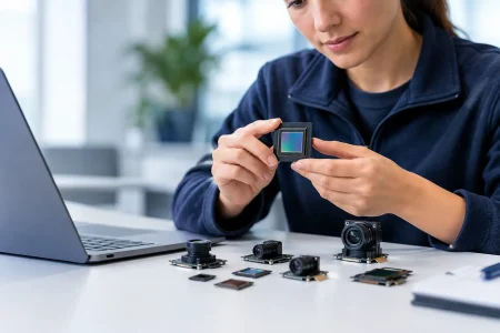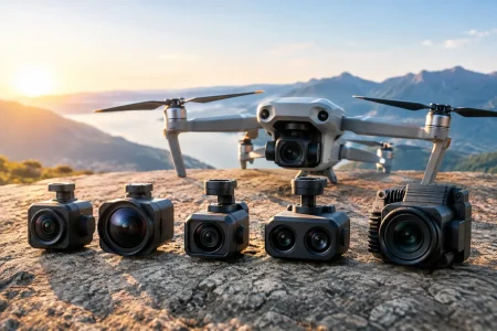

A stereo module review should begin with one practical question: can this camera pair produce dependable depth data in the exact environment where the finished device will operate? Resolution, sensor name, and baseline distance matter, but they do not independently determine real-world performance. For robotics, inspection equipment, medical devices, and smart infrastructure, stereo depth is only as useful as its calibration stability, optical consistency, synchronization, and integration quality.
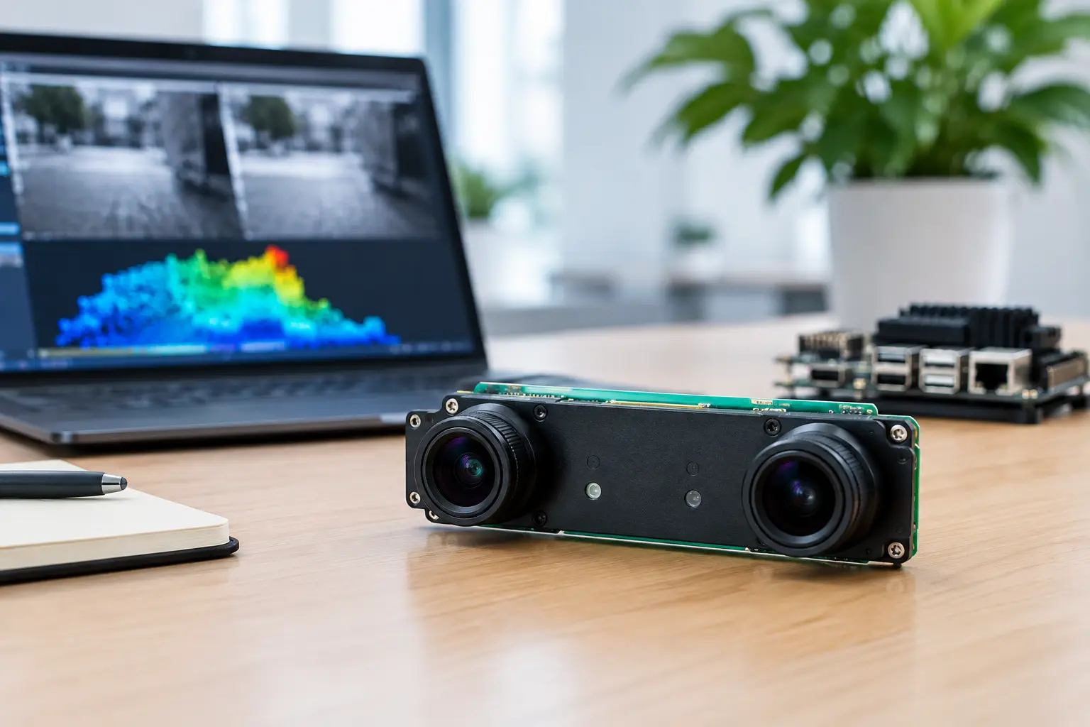
Stereo modules give a device two viewpoints of the same scene. Software measures the displacement of matching image features between the left and right images, then calculates distance. The principle is established, but implementation is demanding. A module that performs well on a controlled desktop target can lose depth accuracy on reflective metal, low-texture surfaces, moving objects, or changing temperatures.
What a Stereo Module Review Must Measure
A meaningful evaluation goes beyond checking whether the two cameras produce pictures. The first requirement is repeatable depth performance across the intended working range. A warehouse robot may need reliable detection from a short pickup distance to several meters ahead, while a benchtop inspection system may prioritize millimeter-level measurement in a narrow field of view. These are different optical and mechanical design problems.
Baseline is a central trade-off. A wider distance between the two camera centers generally improves depth discrimination at longer ranges because the disparity between views is larger. However, a wider baseline increases module size and can create more occlusion, where one camera sees a feature that the other cannot. Compact handheld devices, endoscopes, and small robotic grippers often require a short baseline and must accept a more limited effective depth range.
Sensor selection also deserves closer review than a megapixel comparison. Matched sensors should have consistent pixel size, response characteristics, frame timing, and exposure behavior. If the left and right channels respond differently to the same illumination, feature matching becomes less stable. Global shutter sensors are usually the stronger choice for fast-moving machinery, mobile robots, and conveyor applications because they capture the entire frame at one instant. Rolling shutter sensors can be appropriate for static scenes or cost-sensitive designs, but motion can introduce geometric distortion that degrades depth calculations.
Optical Matching Is Not Optional
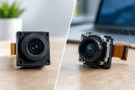
Stereo algorithms assume that corresponding points in both images describe the same geometry. That assumption weakens when lens distortion, focal length, focus position, or field of view differ between channels. A stereo module should use optically matched lenses and controlled assembly processes to keep the two imaging paths consistent.
Review the lens specification as a system rather than treating it as a separate purchase decision. A wide-angle lens captures more scene information but introduces stronger distortion and may reduce pixel density on distant targets. A narrower lens can improve detail at a target distance but reduces overall coverage. The correct choice depends on where objects appear in the device workflow, not on which specification looks larger on a data sheet.
Fixed focus is often the most reliable option for production stereo systems when the operating range is known. It reduces mechanical complexity and avoids left-right focus mismatch. Autofocus can help in variable-distance imaging, but both channels must remain coordinated. If focus changes independently, calibration assumptions can shift and depth quality may become inconsistent.
Calibration Separates a Camera Pair From a Stereo Product
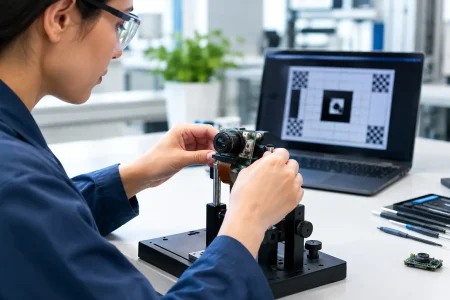
Mechanical alignment alone does not create a production-ready stereo module. Each module needs calibration data that describes intrinsic lens parameters and the precise relationship between the two cameras. This includes focal length, principal point, distortion coefficients, rotation, and translation. The host processor uses these parameters to rectify images so corresponding image points align on the same horizontal lines.
For an engineering team, the important question is not simply whether calibration is available. Ask how it is performed, how the information is delivered, and how it is retained through assembly. Calibration stored in module EEPROM can simplify host integration and reduce the risk of serial-number errors. Factory calibration files can also work, provided the OEM has a disciplined method to track each unit through production.
Calibration must remain stable after vibration, thermal cycling, cable installation, enclosure assembly, and normal product handling. This is why module construction matters. Lens holders, sensor boards, brackets, adhesives, and mounting points all influence alignment over the product life cycle. A low initial calibration error has limited value if the camera relationship shifts after the device leaves the factory.
Depth Accuracy Depends on Scene Conditions
No passive stereo module provides identical results in every scene. It depends on visible texture, illumination, surface material, object edges, and algorithm capability. White plastic, polished metal, clear film, deep shadows, and repeated patterns are all challenging because the software may struggle to identify unique corresponding features.
Active illumination can improve results in low-texture environments. An infrared pattern projector, structured light source, or carefully designed supplemental lighting gives the algorithm more features to match. This adds components, power demand, thermal considerations, and regulatory requirements. It may be the right decision for a fixed industrial station, while a battery-operated mobile device may favor passive stereo with optimized optics and on-device processing.
Interface and Synchronization Review
The interface must match the processing architecture before the module is selected. MIPI CSI-2 is often preferred for compact embedded platforms because it provides high bandwidth with low physical footprint. USB modules can reduce integration effort for PCs, edge computers, and rapid prototypes, particularly when standard UVC compatibility is needed. DVP remains useful for some legacy or cost-focused embedded designs, but available bandwidth can limit resolution and frame rate.
Two synchronized image streams consume substantial bandwidth. Engineers should calculate the full requirement using resolution, frame rate, bit depth, number of channels, overhead, and any compression approach. A module may support two high-resolution sensors, yet the selected processor, cable, or USB controller may not sustain the intended operating mode.
Hardware synchronization is strongly preferred where motion matters. It ensures both sensors begin exposure together, reducing temporal mismatch between the two viewpoints. Software synchronization may be acceptable for slow or static scenes, but it should not be assumed sufficient for mobile robotics, automated guided vehicles, gesture tracking, or high-speed inspection.
Production Readiness in a Stereo Module Review
For procurement and product teams, the strongest stereo design can still become a commercial risk if supply continuity and manufacturing control are weak. Review the sensor lifecycle, lens availability, key component alternates, lead times, and change-control process. A supplier should be able to explain how design revisions are communicated and how consistent optical performance is protected across production lots.
The module should also be evaluated as part of the final mechanical stack. Flat flexible cable routing, connector retention, electromagnetic interference, thermal paths, and enclosure tolerances can affect reliability. A stereo camera that is accurately calibrated before installation may need a different mounting strategy if the finished enclosure introduces stress or misalignment.
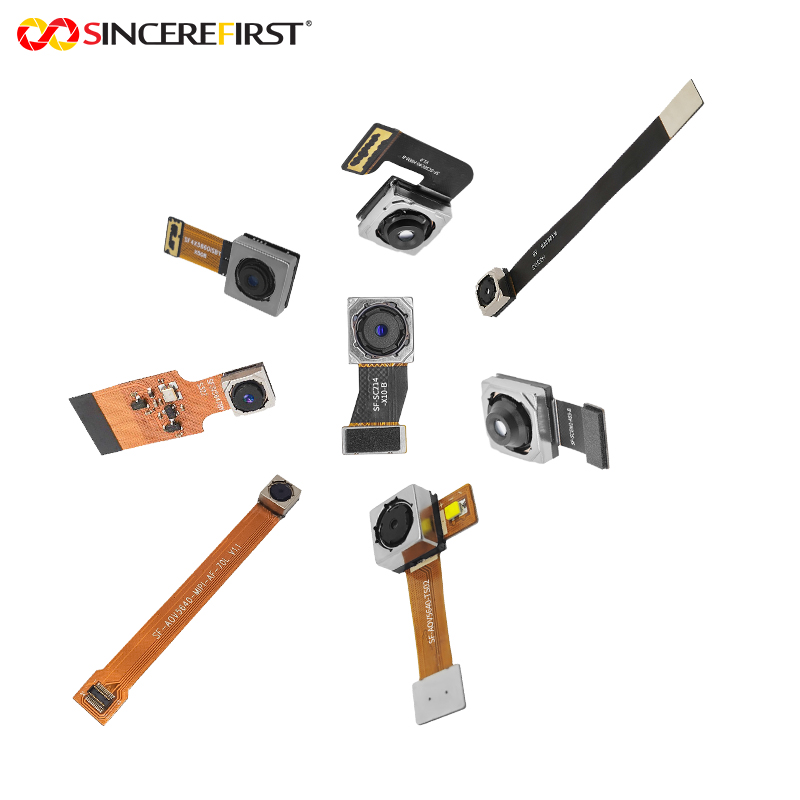
For custom programs, early samples are useful only when they represent a path to volume manufacturing. The best development partner can adjust sensor selection, lens field of view, baseline, board shape, connector orientation, frame rate, and calibration method without treating every requirement as an afterthought. SincereFirst supports this type of engineering-to-production transition with standard camera modules and customized imaging development for embedded applications.
A Practical Evaluation Sequence
Start with the application rather than the camera catalog. Define the nearest and farthest detection distance, required depth precision, target speed, field of view, lighting conditions, size limits, host platform, and expected annual volume. These requirements identify whether a compact short-baseline module, a wider-baseline industrial design, or an active stereo solution is the better fit.
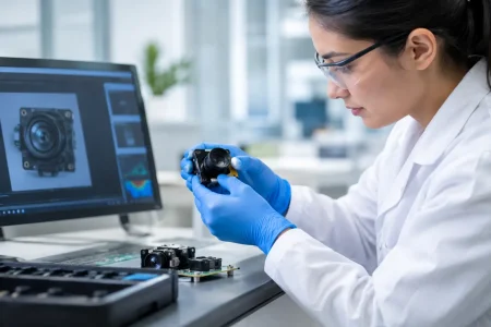
Then test representative samples in the actual scene. Include low light, glare, vibration, expected object materials, and realistic motion. Measure invalid depth pixels, depth noise, latency, frame-to-frame stability, and accuracy at several distances. A single depth map screenshot is not enough evidence for a product decision.
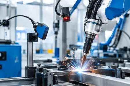
Finally, review the manufacturing path with the same discipline applied to optical performance. Confirm calibration handling, inspection criteria, yield expectations, traceability, supply planning, and support during pilot builds. Stereo vision succeeds when optical design, electronics, software, mechanics, and production control are treated as one system.
The right module is not necessarily the one with the highest advertised resolution or the widest specification list. It is the one that delivers repeatable depth data, fits the host architecture, survives the product environment, and can be built consistently when the program moves from prototype to volume.