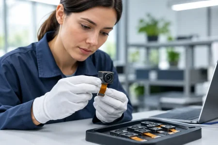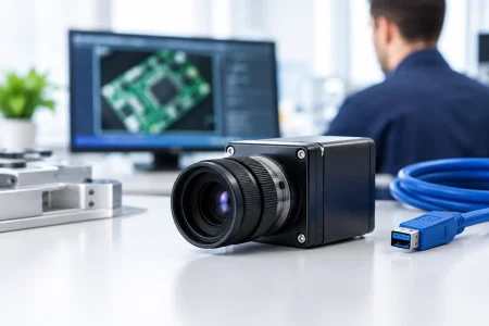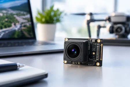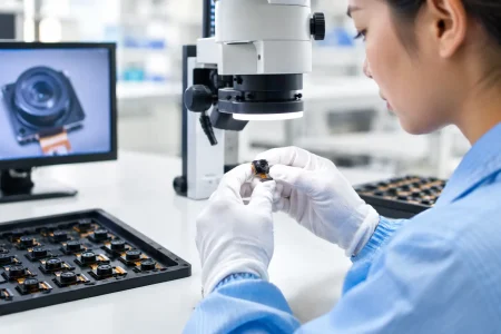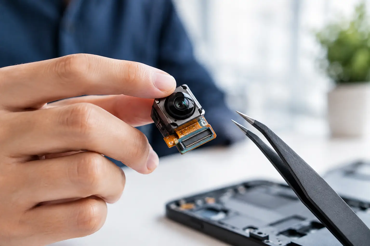
A compact camera can pass image validation on the bench and still fail after 20 minutes inside a sealed robot, medical instrument, or outdoor enclosure. So, do camera modules overheat? They can, particularly when a high-resolution sensor, image signal processor, LEDs, and nearby processors share limited space with no practical path for heat to escape.
Overheating is not simply a camera-module problem. It is a system thermal-design problem that can affect image quality, frame stability, product life, and user safety. For OEM teams, the right question is not whether a module becomes warm. It is whether its operating temperature stays within sensor, lens, flex cable, connector, and surrounding-device limits under the actual workload.
Do Camera Modules Overheat in Real Applications?
Camera modules generate heat whenever electrical power is converted into image capture, data processing, illumination, and transmission. A basic low-power module in an open, ventilated device may show little temperature rise. A 4K USB3.0 or MIPI module operating continuously at high frame rate in a compact metal or plastic housing is a different case.
The sensor itself consumes power, but it is often not the largest heat source. Depending on the architecture, heat may come primarily from the image signal processor, serializer, FPGA, application processor, USB bridge, or LED driver. In endoscope and inspection systems, illumination can be a major thermal load because LEDs sit close to a small camera head and may run for extended periods.
Ambient conditions matter just as much. A module that operates reliably at 25°C in a laboratory can face a much higher internal temperature in a smart-city camera under sunlight, a factory machine near motors and drives, or a diagnostic device used continuously in a warm room. The final specification must account for the worst credible combination of ambient temperature, duty cycle, enclosure, and airflow.
What Heat Does to Camera Performance
Image sensors are temperature-sensitive semiconductor devices. As temperature rises, dark current increases. This can introduce more visible noise, especially in low-light scenes, long-exposure imaging, and high-gain modes. Hot pixels may become more apparent, and the module’s black-level correction or noise-reduction processing may work harder to preserve an acceptable image.
Thermal effects can also change image consistency. Color response, analog gain behavior, autofocus performance, and lens focus position can shift as temperatures move away from calibration conditions. These shifts may be minor in a consumer viewing application but unacceptable in barcode reading, measurement, medical observation, or machine-vision inspection.
At higher temperatures, the system may protect itself by reducing frame rate, limiting processor clocks, disabling LEDs, restarting the camera pipeline, or shutting down. Repeated thermal cycling can also place stress on solder joints, FPC connections, adhesives, lens assemblies, and board-level components. A module may not fail immediately, yet its long-term reliability margin can narrow substantially.
This does not mean every warm module is defective. A measured temperature rise is normal. The engineering concern is sustained operation outside component ratings or performance limits.
The Main Causes of Camera Module Overheating
High data rates and continuous capture
Resolution, frame rate, bit depth, and interface speed all influence power consumption. Streaming 1080p at a modest rate places a different load on the system than continuous 4K capture, multi-camera synchronization, or high-speed industrial imaging. USB3.0, MIPI CSI-2, and Ethernet-based camera designs can all run reliably, but the host-side processing and transport architecture must be sized for the workload.
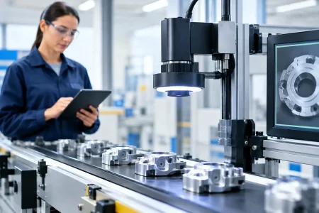
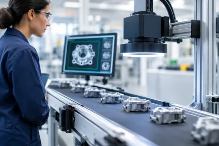
Continuous operation deserves special attention. A camera used for a short user-triggered capture may have time to cool between events. A security camera, autonomous mobile robot, or production-line vision system may run around the clock. Thermal validation must reflect this duty cycle rather than a brief startup test.
Illumination located near the sensor
Integrated LED lighting simplifies mechanical design, especially in endoscope, inspection, and close-range imaging applications. It also concentrates heat in a small volume. Light output, LED drive current, optical efficiency, pulse pattern, and conductive paths through the camera head all affect the resulting temperature.
Reducing LED current can help, but it may reduce usable illumination and image signal. Better optical coupling, pulse-width control, external illumination, or a more efficient sensor can often deliver a stronger system-level result than simply lowering brightness.
Poor enclosure heat transfer
A module mounted in a sealed plastic housing has limited ways to reject heat. Air inside the enclosure quickly reaches equilibrium, and the camera board becomes dependent on conduction through mounting points, chassis surfaces, or dedicated thermal materials.
Metal housings can improve heat spreading, but only when the mechanical interface is designed intentionally. A metal case separated from the heat source by air gaps, low-contact mounting features, or unsuitable pads does little. The thermal path must be continuous from the heat-generating device to a surface that can dissipate energy.
Heat from adjacent electronics
The camera may be operating within specification while a nearby SoC, wireless module, power regulator, display, or motor driver raises the local ambient temperature beyond the camera’s intended condition. This is common in compact smart devices and edge-AI systems, where processing power is concentrated near the imaging path to reduce latency.
Treat the camera as part of a thermal map, not as an isolated board. Measure temperatures at the sensor package, processor or bridge IC, FPC connector, camera-head exterior, and the air volume surrounding the module.
How to Design a Cooler, More Reliable Camera System
Start by defining the imaging requirement precisely. Select the resolution, frame rate, shutter mode, dynamic range, and interface needed for the application, rather than specifying maximum performance by default. Excess resolution or frame rate increases bandwidth, host processing, storage load, and heat without necessarily improving the decision the camera must support.
Next, establish a thermal budget during early architecture work. Identify every heat source, estimate its power at normal and peak operation, and determine where heat can leave the device. A preliminary thermal model is valuable, but it should be followed by measurement on physical samples. Real enclosures, cable routes, adhesive layers, and assembly tolerances can change results significantly.
For compact designs, thermal management normally relies on conduction. Use mechanically stable contact areas, appropriate thermal interface materials, and chassis features that move heat away from the sensor and processing components. Avoid transferring excessive heat toward a user-contact surface or a medical camera tip, where external temperature limits may be stricter than electronics limits.
Firmware and system controls provide another useful layer. Adaptive frame rates, LED dimming, event-triggered capture, idle modes, and thermal alarms can reduce heat during demanding conditions. These measures should support a sound mechanical design, not compensate for a poorly sized enclosure.
A practical validation plan should include the following four conditions:
- Cold start at the highest expected ambient temperature.
- Continuous capture at maximum intended resolution, frame rate, and illumination level.
- Peak processing and communication activity with nearby electronics enabled.
- Repeated power and thermal cycles to identify drift, instability, or mechanical stress.
During these tests, record not only component temperature but also image metrics. Noise level, hot-pixel behavior, color consistency, frame drops, USB or MIPI errors, focus stability, and shutdown events reveal whether thermal performance is acceptable for the end use.
Specifying a Camera Module for Thermal Margin
When qualifying a supplier, ask for more than a general operating-temperature range. Confirm which component establishes the limit and whether the stated range applies to ambient temperature, board temperature, or sensor junction temperature. These values are not interchangeable.
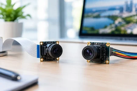
Also discuss the final mechanical arrangement early. A supplier can recommend suitable sensor formats, interface options, FPC lengths, board layouts, illumination strategies, and heat-spreading features when enclosure constraints are known before tooling. For custom modules, that collaboration can prevent a late redesign caused by noise, focus drift, or thermal shutdown during system testing.
SincereFirst supports this engineering process with configurable embedded camera modules and custom imaging development for industrial, medical, robotics, and smart-device programs. The best module is not merely the smallest one that fits. It is the module that delivers stable image output and manufacturable reliability at the intended operating load.
Thermal margin should be treated as a product requirement from the first prototype. If the camera has a clear path to shed heat, the sensor is matched to the workload, and the complete device is tested under real operating conditions, a compact imaging system can run reliably for the long service life commercial products demand.