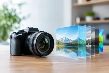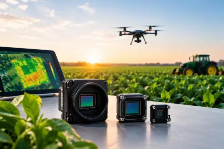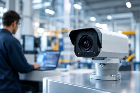
A quality inspection example for a camera module is not a simple pass-or-fail check at the end of a production line. For an OEM building a medical device, robot, industrial scanner, or security terminal, the camera module must meet optical, electrical, mechanical, and reliability requirements at the same time. A module can power on and still fail in the field because of dust on the sensor, unstable focus, a damaged FPC cable, or image noise that appears only at a specified temperature.
The following example shows how a practical inspection plan can be structured for a MIPI or USB camera module. The exact thresholds should always be defined around the end device, sensor, lens, interface, illumination environment, and production risk level.
Quality Inspection Example: 5 MP MIPI Camera Module
Assume an OEM requires a compact 5 MP MIPI camera module for a handheld industrial inspection device. The module uses a CMOS image sensor, fixed-focus lens, FPC assembly, and MIPI CSI-2 output. It will operate at close and mid-range working distances, where edge sharpness and stable color performance matter as much as resolution.
The inspection plan begins before production and continues through shipment. Its purpose is to prevent variation from reaching final assembly, while also creating records that help engineers trace an issue back to a component lot, process station, or test condition.
1. Incoming material inspection
Incoming inspection verifies that the parts used to build the module match approved specifications. This includes the image sensor, lens assembly, printed circuit board, FPC, connector, adhesive, infrared filter, and packaging materials. A supplier certificate is useful, but it does not replace sample-based verification.
For the CMOS sensor, inspectors confirm the correct part number, lot identification, package condition, and critical electrical characteristics. For lenses, the team checks focal length, field of view, thread condition, lens barrel dimensions, and visible contamination. A small change in lens batch performance can affect focus margin, distortion, and shading correction across the finished product.
The FPC and connector deserve close attention. Inspectors check pad finish, conductor alignment, bend areas, reinforcement plate position, and connector mating dimensions. In compact devices, mechanical stress at the cable transition is a frequent cause of intermittent image output. Material inspection should therefore include both visual checks and dimensional measurement against controlled drawings.
2. In-process assembly control
Camera module assembly requires controlled handling because the sensor surface and lens optical path are vulnerable to particles, fingerprints, and adhesive vapor. Cleanroom or controlled clean-area production reduces contamination risk, but process discipline remains essential.
During SMT and sensor attachment, automated optical inspection can confirm component placement, solder quality, polarity, and obvious bridge defects. After lens installation, the module moves to active alignment or focus adjustment. The production fixture powers the module, displays a calibrated target, and measures image sharpness at the required working distance.
For this 5 MP inspection module, the manufacturer may set a minimum center and corner sharpness threshold based on spatial frequency response. A module that meets center sharpness but falls below the corner requirement may create a blind area when the operator is inspecting edges, threads, or small surface defects. The acceptable balance depends on the application. A barcode reader may prioritize center-zone clarity, while a wide-area machine vision system may require stronger corner performance.
Adhesive curing is another controlled step. Too little cure can allow the lens position to drift. Too much heat or an unsuitable adhesive can introduce lens tilt, stress the sensor package, or produce volatile residue on internal optical surfaces. A capable process records cure time, temperature, and material lot as part of the manufacturing traveler.
3. Electrical and functional testing
Every completed module should undergo functional testing with the intended interface and a validated test fixture. For a MIPI camera module, the fixture confirms that the module initializes correctly, communicates through the required lane configuration, and outputs the specified resolution and frame rate.
Typical functional checks include power consumption, startup behavior, I2C communication, MIPI data output, frame stability, register configuration, and image capture. The test system should identify faults such as missing lines, frame tearing, intermittent output, abnormal current draw, or failure to respond after repeated power cycles.
Testing should not rely solely on a live preview image. A preview can make a marginal module appear acceptable. Automated software analysis provides repeatable results by measuring values against defined limits. For example, the system can calculate average luminance, color channel balance, dead or stuck pixel count, signal-to-noise ratio, and fixed-pattern noise under controlled lighting.
4. Optical image-quality verification
Optical verification is where a camera module inspection becomes application-specific. The right test chart, lighting geometry, target distance, and software algorithm must reflect the conditions the customer expects in the finished device.
In this example, the module is tested with a resolution chart, uniform light source, color target, and distortion target. The quality team evaluates focus performance, field of view, white balance consistency, color reproduction, vignetting, distortion, and shading. It also checks for dust, scratches, stains, and foreign particles that may be visible in the image.
A useful acceptance rule separates permanent image defects from transient artifacts. A bright spot that remains in the same pixel location across multiple frames may indicate a defective pixel or sensor contamination. A mark that changes position may come from the test environment, fixture, or target. This distinction prevents false failures while ensuring true optical defects are contained.
Low-light performance should be tested when the final application operates in variable illumination. Higher gain can improve visibility, but it also increases noise and may reduce usable detail. There is no universal “good” noise level. The correct threshold depends on whether the camera is supporting human viewing, machine vision algorithms, recording, or measurement.
What Makes This Quality Inspection Example Traceable
A strong inspection process creates evidence, not just a green test result. Each camera module should carry a serial number or traceable code connected to its sensor lot, lens lot, PCB lot, key process parameters, test station, test date, and inspection outcome.
If a customer later reports color drift or unstable output, traceability allows the manufacturer to compare affected modules with production records. The team can determine whether the issue is isolated to a sensor batch, lens supplier, firmware revision, assembly shift, or specific test fixture. Without this data, corrective action becomes slower and more expensive.
For high-risk applications such as medical imaging, industrial measurement, or long-life infrastructure equipment, traceability should also include retained test images and measurement results. The level of record retention depends on contractual, regulatory, and product-life requirements. Keeping every image from every unit may not be necessary for a high-volume consumer device, but retaining meaningful test data is still valuable for yield analysis and customer support.
Reliability Checks Before Release
Final inspection confirms that the module shipped matches the approved configuration and has passed all required tests. Reliability sampling goes further by challenging selected production units beyond normal operating conditions.
Depending on the product specification, this may include thermal cycling, high- and low-temperature operation, vibration, mechanical shock, bend testing for FPC assemblies, humidity exposure, connector insertion cycles, and extended power-on aging. These tests do not replace 100% functional inspection. They validate whether the manufacturing design and process are likely to remain stable over time.
For example, a camera module can pass room-temperature image testing but lose focus after repeated temperature changes if the lens barrel, adhesive, and holder expand at different rates. That risk is particularly relevant for vehicle-adjacent equipment, outdoor security devices, agricultural systems, and industrial equipment used near heat sources.
Packaging is also part of release quality. Modules should be protected from electrostatic discharge, moisture, physical impact, and optical contamination during transport. A carefully tested module can still arrive unusable if tray design, protective film, or ESD handling is inadequate.
Turning Inspection Results Into Better Supply Performance
The value of inspection is not limited to rejecting defective units. Yield data can reveal trends before they become customer failures. If corner sharpness trends downward over several lots, engineering can investigate lens tooling wear, active-alignment calibration, or incoming lens variation. If a connector failure rate rises, procurement and quality teams can contain the affected lot before final assembly is disrupted.
For buyers, the key question is not whether a supplier says it performs quality control. Ask what is inspected, at what stage, with which equipment, against which acceptance criteria, and how results are traced to each shipment. SincereFirst applies this engineering-led approach to standard and customized camera modules because reliable imaging starts with a controlled process, not a final visual check.
A well-defined inspection plan should evolve with the product. As the end device changes, update the test conditions to reflect the real optical, electrical, and mechanical risks the camera module must handle.