
A welding cell can produce an acceptable bead for hours, then lose its margin when a fixture shifts, a joint gap changes, or spatter obscures the torch path. The top sensors for welding are not simply add-ons for inspection. They provide the measurement data that lets an automated cell locate a joint, control the process, identify defects, and document production quality before poor parts move downstream.
For OEMs, system integrators, and manufacturers building automated welding equipment, the right sensor choice starts with the question being measured. Joint position, bead geometry, arc stability, temperature, and completed-weld quality are different problems. A single camera rarely solves all of them. The most effective systems combine sensing technologies around a defined control strategy, selected for the welding process, material, cycle time, and required traceability.
Top Sensors for Welding Automation
1. Laser seam tracking sensors
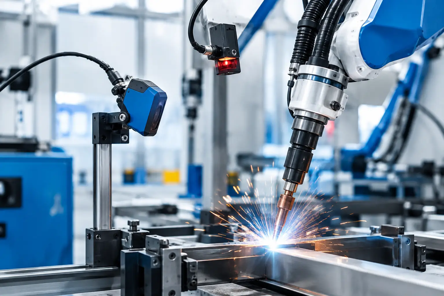
Laser seam tracking is often the first choice when the cell must find a variable joint before or during welding. A projected laser line creates a cross-sectional profile of the workpiece, while a camera analyzes the line deformation to calculate seam location, gap, groove angle, height, and offset. The robot or motion controller can then correct the torch path in real time.
These sensors are especially useful for fillet welds, lap joints, butt joints, and V-grooves where part presentation varies. They can compensate for fixture tolerance, thermal distortion, and normal lot-to-lot variation that would otherwise require tighter, more expensive tooling.
The trade-off is integration complexity. The sensor needs a stable mounting position, known geometry relative to the torch, and calibration to the robot coordinate system. Reflective materials, heavy scale, and arc light can also affect the measurement. Buyers should evaluate profile rate, working distance, laser wavelength, measurement range, and the supplier’s filtering performance under realistic weld conditions rather than reviewing a clean demonstration sample.
2. Weld cameras for visual process monitoring
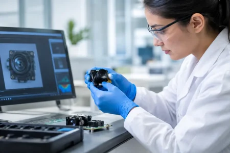
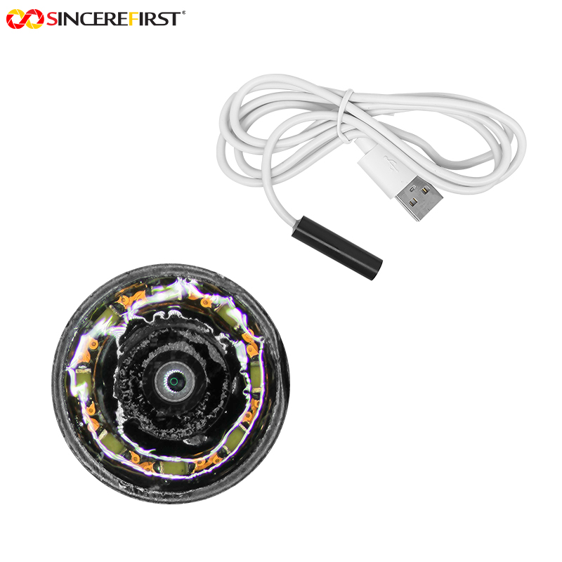
Industrial weld cameras give operators and automated systems a direct view of the arc, puddle, filler wire, and joint area. Depending on the application, a camera may be mounted near the torch, through a protective viewing path, or at a wider angle for cell-level observation. High dynamic range imaging and carefully selected optical filters help retain useful image information despite the intense brightness of an arc.
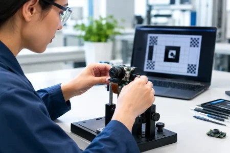
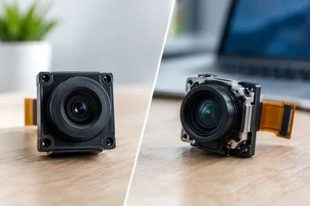
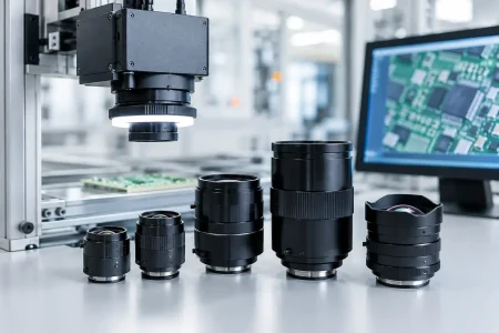
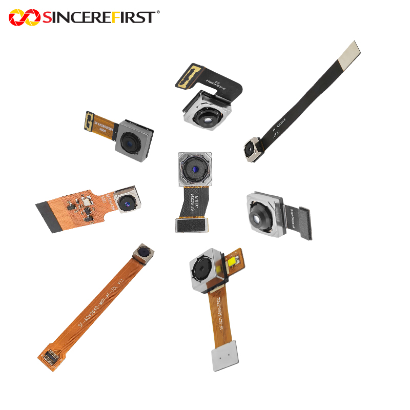
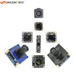
For machine builders, camera selection is an optical and mechanical decision as much as a resolution decision. Global shutter sensors are often preferable where fast motion must be frozen without distortion. High frame rates can capture fast-changing puddle behavior, while compact MIPI, USB, or customized board-level camera modules may be better suited to constrained torch-mounted housings.
Visible-light cameras work well for general observation and many post-weld tasks, but they are not automatically reliable for in-process puddle measurement. Arc glare, smoke, spatter, and changing surface reflectivity create difficult imaging conditions. A purpose-built optical path with bandpass filtering, protective windows, controlled illumination, and image-processing validation is usually required.
3. Infrared and thermal sensors
Thermal sensing measures heat rather than geometry. Infrared cameras, spot pyrometers, and thermal arrays can monitor preheat, interpass temperature, cooling behavior, heat-affected zones, and consistency across repeated welds. This is valuable where heat input affects metallurgical performance, distortion, coating damage, or downstream assembly quality.
A thermal camera provides a temperature map, making it useful for research, process development, and inspection of larger areas. A pyrometer provides a focused, fast temperature measurement and can be easier to install when only one critical point matters. Both approaches require attention to emissivity. The temperature reported by an infrared device depends on the material surface, finish, oxidation state, and viewing angle. Calibration against the actual production material is essential.
Thermal monitoring is not a substitute for seam tracking. It can indicate that a process is drifting, but it does not directly tell the robot where the joint is. It delivers the most value when paired with electrical process data or vision-based positional measurement.
4. Arc voltage and welding current sensors
Voltage and current sensing remain among the most practical tools for monitoring arc-based welding processes. These measurements reveal whether the power source is delivering the expected energy and can identify events such as unstable arc transfer, excessive stick-out variation, poor grounding, wire-feed problems, or missing weld segments.
Because these signals are already close to the welding power source, they are typically easier to acquire than optical data. Their limitation is indirectness. A current waveform may show that an arc occurred, yet it cannot confirm final bead shape or penetration by itself. Signal interpretation also changes by process. MIG, TIG, resistance welding, and plasma welding each have different normal operating signatures.
For production systems, electrical sensing should be time-synchronized with robot position, torch speed, wire feed, and part identification. That transforms raw waveform data into traceable weld records and makes it possible to isolate recurring issues by station, program, consumable batch, or component lot.
5. Resistance welding force and displacement sensors
Resistance spot welding requires a different sensing approach than arc welding. Electrode force, displacement, current, voltage, and weld time are core process variables. Force sensors verify clamping behavior, while displacement sensors help assess stack-up, electrode wear, sheet collapse, and nugget formation trends.
A displacement curve can expose changes that are not obvious from current alone. For example, a worn electrode may alter the contact area and heating behavior long before a visual inspection program detects a problem. These measurements are especially relevant in high-volume automotive, appliance, and battery-component production where repeatability and complete traceability are expected.
Sensor selection must account for high current, electromagnetic interference, mechanical shock, and short cycle times. The measurement chain should use appropriate shielding, isolation, and sampling rates. A sensor with excellent lab accuracy but poor electrical noise immunity can create false rejects on the line.
6. Post-weld 2D and 3D inspection sensors
Not every defect can be controlled while welding, so final inspection remains necessary. Two-dimensional cameras can inspect bead presence, weld length, surface discontinuities, spatter, component orientation, and marking readability. They are cost-effective when the feature is visible and lighting can be controlled.
Three-dimensional laser profilers and structured-light systems add height data. They can measure bead width, reinforcement, undercut, overlap, crater geometry, and relative weld position. This is the stronger option when acceptance criteria depend on geometry rather than appearance alone.
The choice between 2D and 3D depends on the defect mode. If the requirement is confirming that a bead exists in the correct location, a properly illuminated 2D vision system may be sufficient. If the application requires quantitative profile measurement, 3D sensing is worth the added cost and integration effort.
How to Select a Welding Sensor Stack
Start with the failure mode that costs the most. A robotic cell missing a seam because of part variation needs joint-location sensing. A line producing inconsistent heat input needs electrical and thermal data. A customer requiring documented bead dimensions needs post-weld 3D inspection. This approach prevents an expensive camera system from being used where a simpler process sensor would perform better.
Next, evaluate the environment honestly. Welding creates arc radiation, smoke, vibration, heat, electromagnetic interference, and spatter. Sensor housings, lenses, windows, cable routing, air purging, and service access matter as much as the data sheet. A compact camera module may meet image requirements but still need a custom enclosure, lens arrangement, and interface board before it is suitable for a production torch.
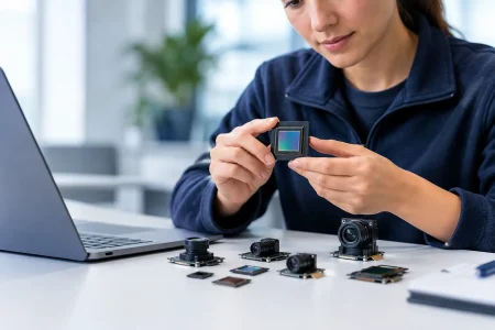
Integration architecture also determines long-term value. Consider the interface required by the controller, whether the system needs deterministic triggering, available processing capacity, and how sensor data will be linked to the part serial number. USB cameras may simplify prototype development, while MIPI or other embedded interfaces can reduce size and latency in an OEM product. For specialized visual monitoring, a custom imaging supplier such as SincereFirst can align sensor selection, optics, module form factor, and manufacturing requirements early in the design cycle.
Finally, validate on real parts at production speed. Test different surface finishes, expected gap variation, deliberate fixture offsets, worn consumables, and realistic smoke conditions. Ask not only whether the sensor detects a defect, but whether it produces stable data that the control system can act on without creating nuisance alarms.
The best welding sensor is the one that turns a known production risk into a measurable, repeatable decision. Define that decision first, then build the imaging and sensing system around it.