
A DVP camera review should not begin with a resolution number. For an embedded product team, a parallel camera module succeeds only when its sensor output, host timing, optics, mechanical envelope, and production controls work together in the final device. A 2MP module can be the right choice for a compact industrial controller, while a higher-resolution part may create unnecessary memory, bandwidth, and tuning demands. The practical question is whether the module delivers repeatable images at the required frame rate under actual operating conditions.
What a DVP Camera Review Must Measure
DVP, or Digital Video Port, transfers image data through a parallel interface. Typical signals include an 8-, 10-, or 12-bit data bus, pixel clock (PCLK), horizontal synchronization (HSYNC), vertical synchronization (VSYNC), and sometimes data enable (DE). It remains a sound interface choice for MCUs, application processors, FPGAs, and legacy embedded platforms with native parallel camera inputs.
A useful review separates camera performance from system performance. The module may output valid frames on a supplier evaluation board yet fail in the customer device because of a mismatched clock edge, incorrect voltage domain, poor routing, or host buffer limitations. Reviewing only the datasheet misses the integration risks that cause late-stage redesigns.
Start by confirming the requested output mode. The sensor may support RAW Bayer, YUV422, RGB565, JPEG, or several windowing and binning modes, but the host must accept the exact format at the target frame rate. If the processor lacks an image signal processor, RAW output shifts demosaicing, color correction, noise reduction, and exposure behavior into the software or FPGA workload. For many cost-sensitive products, YUV output from a sensor with an integrated ISP is more practical, even if it provides less tuning freedom.
Check the Timing Budget Before Selecting a Sensor
Pixel clock is the first calculation that deserves attention. It is affected by active resolution, blanking intervals, frame rate, and the sensor timing configuration. Do not compare only the advertised frames per second. Confirm the actual PCLK, polarity settings, setup and hold requirements, and whether the host can sustain capture without dropping frames.
The interface also needs a defined electrical plan. Camera modules commonly operate with several rails, such as 1.8V for I/O or core logic and 2.8V for analog circuitry, while the host may use 3.3V I/O. Level shifting can solve a voltage mismatch, but it adds propagation delay, power consumption, board area, and another source of signal degradation. A better design may be a sensor or module configuration aligned with the host I/O voltage from the beginning.
Parallel buses are simpler to inspect than high-speed serial lanes, but they are not forgiving of careless layout. PCLK and data lines need controlled routing, sensible length matching, a clean return path, and distance from switching power supplies or high-current traces. The permissible mismatch depends on PCLK frequency and receiver margin. An experienced module supplier should provide pin definitions, timing diagrams, recommended routing practices, and a clear explanation of any assumptions used during validation.
Image Quality: Review the Whole Optical Stack
Sensor resolution alone does not define usable image quality. The lens, field of view, focus distance, infrared filter, sensor pixel size, and image processing all influence what the final product can detect. A review should use representative targets at the actual working distance, not only images of a well-lit test chart captured at close range.
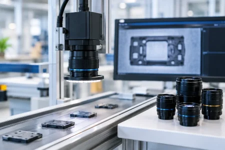
For barcode reading, board inspection, security devices, agricultural equipment, and medical accessories, test the details that matter to the application. That can include low-contrast edge definition, motion blur, glare from reflective surfaces, color stability under LEDs, or the ability to resolve a feature near the edge of the field. A wide-angle lens may cover more of a scene but introduce barrel distortion that reduces measurement accuracy. A narrow field of view can improve detail but may demand tighter mechanical alignment.
Low-light claims also require context. Ask for exposure time, gain level, illumination, frame rate, and noise-reduction settings used for the sample image. Longer exposure can improve brightness, yet it will blur moving objects. High analog or digital gain can reveal a target, but it also raises visible noise and may make downstream vision algorithms less reliable. There is no universal winner between sensitivity, motion performance, and noise. The correct balance depends on the device environment.
Focus is another frequent source of confusion. Fixed-focus modules are efficient for controlled working distances and high-volume production, but their depth of field must be verified against the product requirement. Auto-focus modules support changing subject distance but require actuator control, tuning, more power, and additional mechanical clearance. For a scanner or inspection tool, fixed focus is often the more dependable production decision when the target range is known.
DVP Camera Review Checklist for Integration Teams
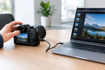
Before design lock, the camera should be tested with the intended processor board, display or algorithm path, enclosure, and illumination. A paper review is not enough. The goal is to establish a controlled baseline that engineering, sourcing, and manufacturing teams can all use.
The test plan should cover at least these areas:
- Interface operation: Validate PCLK frequency, sync polarity, bit depth, output format, I2C register access, reset behavior, and power-up sequence.
- Image behavior: Capture static and moving scenes across expected lighting conditions, working distances, temperatures, and exposure settings.
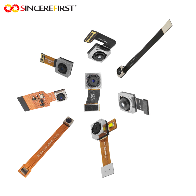
- Mechanical fit: Check connector orientation, FPC bend radius, module keep-out zones, lens height, mounting tolerance, and tolerance to shock or vibration where relevant.
- Production consistency: Define acceptable focus variation, lens shading, dead-pixel criteria, cosmetic requirements, serial traceability, and outgoing inspection standards.
This process identifies trade-offs early. For example, moving from an 8-bit to a 10-bit DVP output may improve tonal precision for a measurement application, but it increases bus width requirements and can complicate host support. Changing from a standard lens to a custom focal length may solve a field-of-view issue but adds optical qualification time. These are commercial and engineering decisions, not just specification choices.
Assess Firmware and Bring-Up Support
A DVP module is not ready for an OEM program merely because it powers on. The supplier should be able to provide an initialization register set for the selected sensor mode, guidance on I2C addressing, and support for image orientation, frame rate, exposure, gain, and test-pattern configuration. If the application requires a particular color response or low-light behavior, confirm what tuning can be changed at the module level and what must be handled by the host.
Review the sensor lifecycle as well. Some camera sensors have limited availability windows or are revised without warning. For products expected to ship for several years, ask about supply planning, approved alternates, and the impact of a sensor change on optics, firmware, compliance, and image output. A pin-compatible replacement is not necessarily image-compatible.
Manufacturing Readiness Is Part of Camera Performance
A promising engineering sample does not guarantee consistent volume output. Camera module manufacturing requires control over lens assembly, focus lock, dust prevention, sensor handling, FPC or board assembly, electrical testing, and final visual inspection. Even small shifts in lens position can change focus performance, especially in compact modules with short focal lengths and tight depth-of-field requirements.
During supplier qualification, request clarity on sample-to-mass-production transition. The key questions are whether the module uses stable materials, how focus is controlled and verified, what functional tests are performed, how lots are traced, and how nonconforming units are managed. Cleanroom processes and automated inspection matter when the application is sensitive to particles, optical contamination, or cosmetic defects.
Customization also needs boundaries. A supplier may change lens field of view, cable length, connector type, pinout, board shape, LED arrangement, or sensor configuration, but every change affects validation. Fast samples are valuable only if the resulting design can be manufactured repeatedly at the planned volume. For OEM teams, the strongest supplier is one that can move quickly during prototyping while documenting the design controls needed for scale.
SincereFirst approaches DVP module development as an integration and manufacturing task, combining camera selection, optical configuration, interface support, and production planning for embedded vision programs. That approach is particularly valuable when a standard module needs a different lens, FPC layout, connector position, or image-output configuration.
When DVP Is Still the Right Interface
DVP is often dismissed in favor of MIPI CSI-2, especially for newer mobile-class processors. MIPI is usually the better fit for high-resolution, high-frame-rate designs where pin count and bandwidth are critical. However, DVP remains practical where the host platform already exposes a parallel camera interface, image data rates are moderate, firmware resources favor a familiar capture path, or the product needs a straightforward interface for an FPGA or industrial controller.
The deciding factor is not whether DVP is newer or older. It is whether the interface matches the processor, bandwidth, board architecture, power budget, and product lifecycle. Selecting DVP for a constrained embedded platform can reduce integration work. Selecting it for a bandwidth-heavy vision task can create a ceiling that appears only after the rest of the system is built.
Treat the review as a design gate, not a supplier comparison exercise. A module that produces stable, correctly timed, application-relevant images on the target hardware is worth more than a better-looking datasheet. That evidence gives your team a clearer path from first sample to dependable production.