

A USB camera can deliver sharp images at the expected frame rate and still fail a product requirement because the image arrives too late. When teams test USB camera latency, they need to measure the full path from a real-world event to the frame available to the application or display – not simply the advertised frame rate.
For industrial automation, robotics, medical visualization, security response, and inspection equipment, a few extra frames of delay can affect control decisions, operator confidence, and system safety margins. A credible latency test separates camera-module behavior from host processing and display delay, then produces a repeatable number that engineering and procurement teams can use during supplier qualification.
What USB Camera Latency Actually Measures
Camera latency is the elapsed time between a visual event and the point at which that event is usable in the target system. The exact endpoint matters. A module supplier may measure latency to the first USB packet. A software team may measure it when a complete frame reaches the application. The end user experiences latency only when the updated image appears on a monitor.
These are different measurements. A useful test plan states its start and end points before any equipment is connected. Common definitions include sensor exposure start to frame delivery at the host, sensor exposure start to application callback, and visual event to display update. For closed-loop machines, the most relevant metric may be event to control decision rather than event to display.
Frame rate alone cannot predict latency. At 30 frames per second, each frame period is 33.3 ms. An image sensor may wait nearly one full frame period before beginning the next exposure. The camera can then add internal processing, frame buffering, USB transfer time, and driver buffering. A 60 fps camera often has a lower latency opportunity than a 30 fps camera, but only if its firmware and host pipeline avoid adding extra queued frames.
Define the Test USB Camera Latency Requirement First
Before selecting a method, define the operating conditions that match the finished product. Test results obtained at a low resolution, bright light level, and lightly loaded development PC may not represent a deployed device running image processing, storage, and user-interface software at the same time.
Record the camera model, sensor mode, resolution, frame rate, pixel format, exposure setting, gain, USB interface version, cable length, operating system, driver version, host controller, and application framework. If the camera supports MJPEG, YUY2, H.264, or other output formats, test each format that the product may use. Compression can reduce USB bandwidth demand, but encoding and decoding can add delay and variability.
Also decide whether the criterion is average latency, maximum latency, or latency variation. Average delay is useful, but the slowest frames often matter more in real-time systems. A robotic pick-and-place system may tolerate a consistent 80 ms delay if compensation is possible, while intermittent 200 ms spikes can cause misses.
Choose a Measurement Method That Matches the Risk
The best test method depends on the accuracy required and the resources available. A quick engineering comparison can use a visible timer. Product release validation should use a controlled optical trigger and a timestamped capture path.
Method 1: LED Event and High-Speed Reference Camera
A practical visual method uses an LED driven by a known electrical signal. Position the USB camera so the LED is visible in its field of view, then use a high-speed reference camera to record both the LED and the system display at the same time. Count the time from LED illumination to the first visible response on the display.
This approach captures end-to-end latency and is easy to explain to non-specialists. Its limitation is that display refresh timing contributes to the result. That is not a flaw when testing user-perceived performance, but it does not isolate the USB camera module.
A high-speed reference camera should run fast enough to provide the needed measurement resolution. At 240 fps, each recorded frame represents about 4.17 ms. For tighter analysis, use a faster reference device or an electronic timing method.
Method 2: LED Event and Host Frame Timestamping
To focus on camera and host delivery, use an LED or strobe controlled by a microcontroller that records the trigger time. In the captured image, detect the first frame where the LED changes state and record the application’s frame-receipt timestamp.
This method is effective for UVC camera evaluation because it removes monitor response from the measurement. However, software timestamps are only meaningful when their location in the pipeline is known. A timestamp taken after color conversion, inference, or rendering will include those operations. Timestamp the frame as close as possible to the capture callback, and document the software layer used.
Method 3: Photodiode-Based End-to-End Test
For high-precision validation, place one photodiode near the event LED and another against a defined area of the display. An oscilloscope or data acquisition unit measures the time between the source light pulse and the corresponding screen change.
This method provides repeatable, sub-frame visibility into end-to-end delay. It is especially valuable for medical displays, machine control interfaces, and other systems where a visual response deadline must be verified. It requires more setup discipline because screen brightness, display area, and threshold settings must remain controlled.
Control the Variables That Create False Results
USB camera latency is often misdiagnosed because the test changes several variables at once. Start with manual exposure and fixed gain. Auto-exposure can lengthen exposure time in dim scenes, changing the time when the sensor can produce a usable image. Auto white balance and noise reduction may also add processing behavior that differs between scenes.
Use the intended USB topology. A camera connected directly to a host port can behave differently from one connected through a hub shared with storage, wireless adapters, or other cameras. USB 2.0 bandwidth is particularly sensitive when multiple high-resolution uncompressed streams share a controller. USB 3.0 provides more bandwidth, but the host controller, cable quality, and application design still determine actual performance.
Rolling-shutter sensors require careful interpretation. The LED may appear first in only part of a frame because rows are exposed at different times. For a consistent result, place the LED in a fixed image location and define whether detection means the first illuminated pixel, a thresholded LED region, or a fully updated frame. Global-shutter sensors simplify motion timing, although total system latency can still be affected by buffering and transport.
Measure at least 100 events rather than relying on a single demonstration. Report the minimum, average, maximum, and a high-percentile result such as the 95th or 99th percentile. This reveals whether delay is stable or whether occasional frame queues, operating-system scheduling, and USB contention are creating unacceptable outliers.
Find the Source of Excess Delay
When latency is higher than expected, divide the pipeline into stages. Sensor exposure time is the first contributor. A 20 ms exposure cannot produce an image immediately after the event, regardless of interface speed. Next, inspect camera firmware behavior. Some modules use one or more frame buffers for image signal processing, scaling, format conversion, or synchronization.
Then examine transport and software. Uncompressed formats demand more USB bandwidth but may avoid codec delay. MJPEG can be a good bandwidth compromise, but host-side decoding adds CPU demand. H.264 can be efficient for recording and remote monitoring, yet it is usually a poor choice for low-latency machine control unless configured specifically for low-delay operation.
Many latency problems sit outside the camera. Video frameworks may queue several frames by default to improve playback smoothness. GPU rendering, display compositing, vertical synchronization, and monitor response can each add a frame or more. If the camera-to-host result is acceptable but the screen result is not, optimize the application and display pipeline rather than changing a camera module that is already meeting its delivery requirement.
Set Acceptance Criteria for Production Programs
A supplier qualification requirement should be written as a measurable condition, not as “low latency.” For example: at 1280 x 720, 60 fps, YUY2 output, manual 5 ms exposure, direct USB 3.0 connection, and specified host hardware, the frame-receipt latency must remain below a defined value for 99 percent of 1,000 trigger events. The requirement should identify whether display delay is included.
This level of detail protects both the buyer and supplier. It prevents a camera from being rejected because of an unreported software queue, and it prevents a good-looking demonstration from masking an unsuitable sensor mode or firmware pipeline. For volume programs, repeat the test across sample lots and validate the final enclosure, cable routing, thermal condition, and processor load.
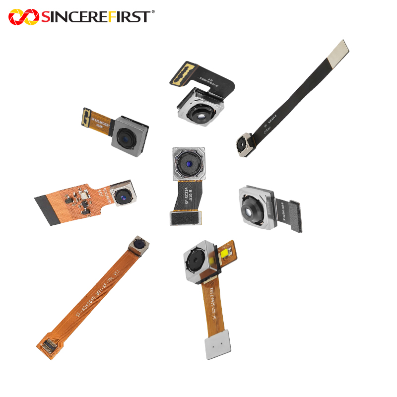
A capable camera partner can help align sensor selection, interface bandwidth, firmware behavior, optics, and mechanical constraints before production. SincereFirst supports this evaluation with USB camera module options and custom imaging development for applications where timing, image quality, and manufacturing consistency must be considered together.
The most useful latency result is not the lowest number achieved on a laboratory bench. It is the repeatable number produced under the same conditions your product will face after deployment.