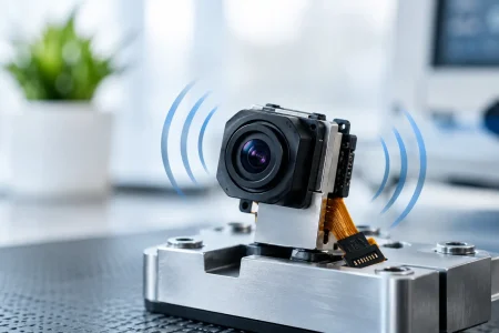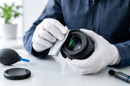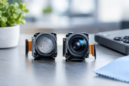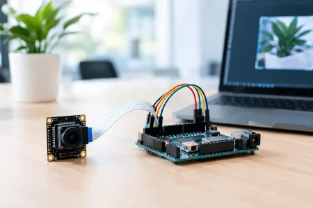

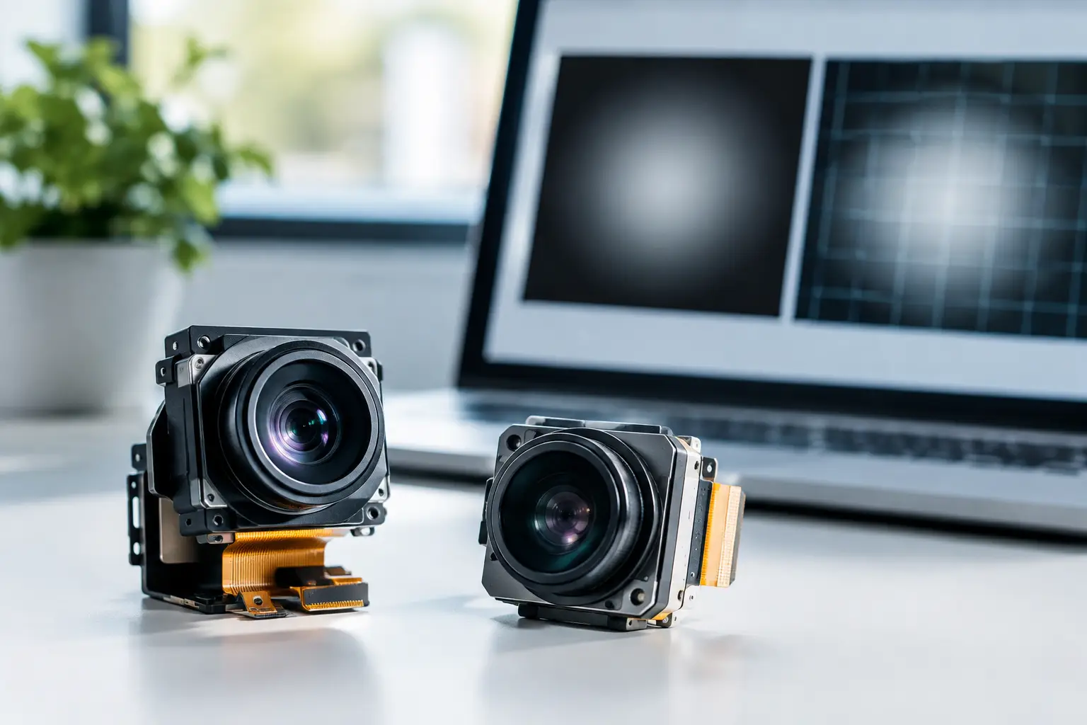
A camera can meet its resolution, frame-rate, and interface requirements on paper yet still produce an image that looks uneven from center to corner. That is where the question, does lens shading matter, becomes a practical engineering and manufacturing decision rather than an optical footnote. For embedded vision products, uncontrolled shading can affect perceived image quality, measurement consistency, and the time required to tune the image signal processor (ISP).
Lens shading is often most visible as vignetting: the image is brighter in the center and darker near the corners. In a finished camera module, however, the effect is not caused by the lens alone. The sensor, lens stack, infrared filter, aperture, mechanical alignment, illumination spectrum, and ISP correction table all contribute. A reliable solution requires evaluating the complete optical assembly.
Does Lens Shading Matter for Embedded Cameras?
Yes, lens shading matters whenever the application depends on uniform brightness, consistent color, or repeatable image processing. Its importance varies by product. A consumer device may tolerate mild corner darkening if the ISP corrects it effectively. A barcode reader, medical camera, industrial inspection system, or machine vision platform may require much tighter control because brightness variation can influence algorithms and operator decisions.
For example, an inspection algorithm that identifies surface defects by contrast may interpret dark corners differently from the center of the field. A document scanner can show visibly uneven white backgrounds. In an endoscope module, uneven illumination and optical shading can reduce detail visibility near the edge of the image. In security cameras, shading may complicate low-light tuning, especially when combined with wide-angle optics and infrared illumination.
The key point is that lens shading is not simply a cosmetic issue. It can become a system-level issue when a camera feeds image analytics, supports diagnostics, captures evidence, or forms part of a calibrated measurement workflow.
What Creates Lens Shading?
The familiar dark-corner pattern has several causes. Natural optical vignetting occurs because light reaching the outer image field travels through the lens at more oblique angles. Mechanical vignetting can occur when a lens barrel, aperture, filter, or housing partially limits off-axis rays. Wide-angle lenses are particularly sensitive because they must collect light across a broad field of view within a compact optical path.
Sensor behavior adds another layer. Image pixels have angular response characteristics, and microlenses above the pixel array are optimized for a specific chief ray angle range. When peripheral rays reach the sensor at steep angles, the corner pixels can collect less light or respond differently by color channel. This is common in compact camera modules where optical height is limited.
Color shading is equally relevant. Red, green, and blue channels may not fall off at the same rate across the field. The result can be a subtle color cast near the image edges even when overall brightness appears acceptable. In applications with white surfaces, skin tones, medical imagery, or controlled inspection lighting, color nonuniformity may be more objectionable than luminance falloff.
Lens Shading Correction Is Part of the Image Pipeline
Most modern camera systems address field nonuniformity through lens shading correction, often called LSC. The ISP applies a position-dependent gain map to raw image data. Pixels that receive less light near the image perimeter are amplified more than pixels near the center. Separate correction values are generally used for each color channel, allowing the system to compensate for both luminance and color shading.
A good correction table is built from measured module behavior, not assumed from a lens specification alone. During calibration, the camera captures a uniform target under controlled illumination. The image data is analyzed to create gain values across the sensor array. Those values are then stored in the module, host system, or ISP configuration.
Correction has limits. Raising gain in dark corners also raises visible noise, particularly in low-light scenes. If the original falloff is severe, software can make the image more uniform but cannot recover photons that never reached the sensor. Strong correction can also expose calibration errors, create corner noise differences, or reduce usable dynamic range.
This is why optical design and ISP tuning should work together. The objective is not to use software as a substitute for sound optics. It is to begin with an optical stack that performs within the system’s tolerance, then use calibrated LSC to refine uniformity.
When Shading Tolerance Should Be Tight
Product teams should define shading requirements early when the camera will operate under controlled or demanding visual conditions. Tight requirements are usually justified for applications such as:
- Industrial inspection and metrology systems that compare pixel values across the field of view.
- Medical and endoscopic imaging where clinicians need consistent detail and color interpretation.
- Document capture, display inspection, and optical character recognition systems with bright, uniform backgrounds.
- Agricultural, robotics, and smart infrastructure systems that rely on stable computer vision performance in changing scenes.
Not every application needs the same specification. A compact, low-cost monitoring camera may prioritize field of view, low-light sensitivity, and total module cost over near-perfect corner uniformity. A high-end diagnostic device may accept a more complex calibration process to maintain a controlled image appearance. The right target is therefore application-specific.
Calibration Must Match the Final Camera Assembly
One of the most common integration mistakes is qualifying a lens, sensor, or ISP independently and assuming the final camera will behave the same way. Lens shading is strongly affected by the assembled stack. A small change in lens position, lens holder geometry, infrared-cut filter thickness, adhesive process, or sensor alignment can change corner response.
For volume production, calibration strategy matters as much as nominal optical performance. A single generic LSC table may be adequate when module-to-module variation is low and application tolerances are broad. Per-module calibration provides stronger consistency, but it adds test time, data handling, traceability requirements, and manufacturing cost.
There is also a middle path. Manufacturers can control lens and sensor tolerances tightly, validate shading across production lots, and apply a family-level correction table when the measured variation remains within specification. This approach can be effective for scaled programs, provided incoming materials, assembly fixtures, and optical test conditions are stable.
At SincereFirst, camera-module development can be evaluated as a complete stack: sensor selection, lens field of view, infrared filter choice, mechanical structure, interface, and image tuning requirements. That approach helps avoid a late-stage situation where an otherwise suitable module requires excessive ISP compensation after the enclosure design is already fixed.
Test Under the Light Your Product Will Actually Use
A lens shading table captured under one light source may not deliver the same result under another. Spectrum matters because red, green, and blue pixels respond differently to various illumination sources. Daylight, warm LEDs, cool LEDs, infrared LEDs, and narrow-band industrial lighting can reveal different color-shading behavior.
Temperature and focus position can matter as well. Compact lens assemblies may shift slightly across operating conditions. If the device uses autofocus, variable aperture, switchable filters, or multiple working distances, the engineering team should confirm whether one calibration profile is sufficient.
For infrared systems, visible-light correction should not be assumed to transfer directly to night mode. The optical path, filter behavior, sensor response, and illumination geometry can change significantly. Security, outdoor monitoring, and machine vision products using IR illumination should validate field uniformity in the actual nighttime configuration.
How to Specify Lens Shading to a Camera Module Supplier
A useful requirement is measurable and tied to system performance. Instead of requesting “low vignetting,” define the field positions to evaluate, the illumination condition, the color temperature or spectrum, the sensor output stage, and the permitted nonuniformity after correction. State whether the requirement applies to raw output, corrected RGB output, or both.
It is also useful to clarify whether corner brightness, color difference, noise increase after correction, and module-to-module consistency are all relevant. For machine vision applications, the requirement may need to include the behavior of the complete imaging path, including illumination and host-side processing.
During sample evaluation, review flat-field images alongside real application scenes. Flat-field tests reveal calibration quality, but real scenes show whether the correction creates visible noise, false color, or tonal discontinuities. Test at the exposure levels, temperatures, and working distances that the final device will use.
The Practical Decision
Lens shading does not need to be eliminated in every camera module. It needs to be understood, measured, and controlled to the level your product requires. A wide-angle module in a compact housing will often show more natural falloff than a narrow-field lens, and accepting some falloff may be the right trade-off for size, cost, or coverage.
The strongest camera designs treat shading as an optical, electronic, and manufacturing parameter from the first prototype. When the lens, sensor, mechanical stack, calibration method, and production test plan are aligned, image uniformity becomes predictable rather than a late-stage tuning problem.