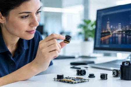
A camera module can meet its resolution target and still fail the product. The usual reason is not the sensor alone. It is a mismatch between optics, illumination, processing bandwidth, thermal limits, mechanical tolerances, and the production test plan. This embedded vision system architecture guide helps engineering teams define those dependencies before a prototype becomes an expensive redesign.
For OEMs building robots, medical instruments, inspection equipment, smart devices, or security products, architecture decisions should begin with the scene and the decision the device must make. A vision system that reads a barcode has different priorities from one that detects surface defects, guides a surgical procedure, or tracks motion in low light. The right architecture is the one that delivers usable image data at the required speed, size, cost, and manufacturing volume.
Start With the Imaging Decision
Define the output before selecting a camera. Is the device presenting live video to an operator, recording evidence, measuring dimensions, detecting objects, or running AI inference at the edge? Each output changes the acceptable trade-offs.
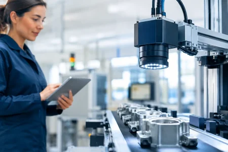
For example, an industrial inspection system may require high shutter speed, controlled lighting, and repeatable lens positioning more than high pixel count. A handheld diagnostic device may prioritize low power, color accuracy, compact board layout, and heat control. A mobile robot may need wide dynamic range, low latency, and synchronized cameras to make navigation decisions safely.
Turn the use case into measurable requirements: working distance, field of view, minimum feature size, target frame rate, motion speed, lighting conditions, acceptable latency, and operating temperature. These values create a practical basis for choosing the sensor, lens, interface, and processor.
The Core Layers of an Embedded Vision System
An embedded vision architecture is a chain. Weakness in one layer limits the value of every layer after it. The core design normally includes image capture, optical control, data transport, processing, software, and production validation.
Sensor and Camera Module
The image sensor determines resolution, pixel size, shutter type, sensitivity, dynamic range, and supported frame rates. CMOS sensors are common in embedded products because they offer compact integration, low power consumption, and broad availability. The final selection still depends on the application.
A rolling shutter sensor can be an efficient choice for stationary scenes, consumer devices, and cost-sensitive products. It can create geometric distortion when the camera or subject moves quickly. Global shutter sensors capture the frame at the same instant, making them more suitable for fast-moving parts, robotic guidance, and metrology. They often bring a cost, sensitivity, or resolution trade-off.
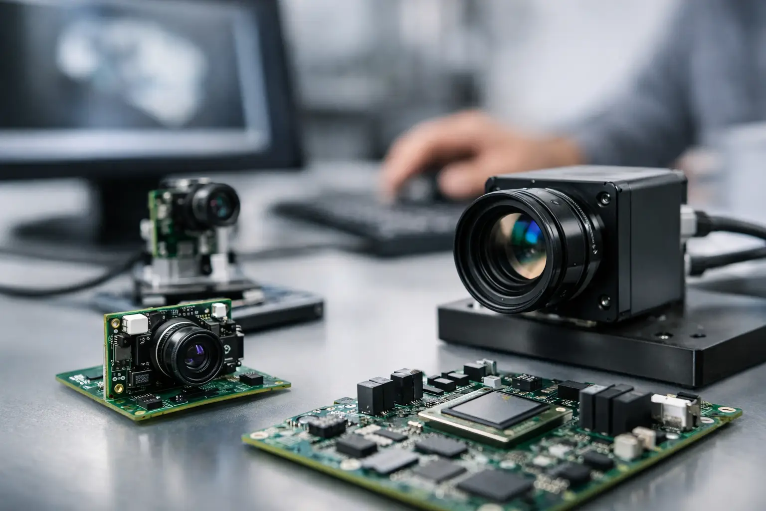
The module itself must fit the mechanical envelope and electrical design. FPC camera modules suit slim or tightly routed devices. MIPI CSI-2 modules support high-speed connection to many embedded processors. USB and UVC camera modules can shorten integration time when a host platform supports them. DVP may remain appropriate for selected legacy or lower-bandwidth designs. The interface should be selected for the whole system, not because a camera sample happens to be available.
Optics and Illumination
Lens selection defines what the sensor can actually see. A high-resolution sensor paired with an unsuitable lens will not produce high-resolution system performance. Evaluate focal length, field of view, distortion, aperture, depth of field, relative illumination, and modulation transfer performance across the full image area.
Working distance matters as much as focal length. If a camera is fixed 150 mm from a part but must inspect a 100 mm area, the lens must deliver that field of view while keeping the required defect size distinguishable. In close-range systems, depth of field can become narrow enough that small product-position changes cause focus loss.
Illumination should be treated as an architectural component, especially in industrial and medical applications. Backlighting can simplify dimensional inspection. Ring or dome lighting can reduce reflections on curved or shiny surfaces. Near-infrared illumination may improve consistency where visible light varies, but it requires sensor and optical components with suitable spectral response. Controlled light often reduces processor complexity because the algorithm receives more repeatable images.
Interface, Bandwidth, and Memory
Data-rate errors are a frequent cause of late-stage performance issues. Calculate image bandwidth using resolution, bit depth, frame rate, overhead, and the number of cameras. A 1920 x 1080 stream at 30 frames per second and 10 bits per pixel is very different from a multi-camera 4K design operating at 60 frames per second.
MIPI CSI-2 is widely used where low latency and direct connection to a mobile or embedded application processor are required. USB 2.0 can be sufficient for modest-resolution video or inspection tasks, while USB 3.0 offers substantially more throughput for higher-resolution streams. Ethernet may be preferred for longer cable runs and distributed industrial equipment, although it introduces different power, networking, and software considerations.
Bandwidth is not only a cable or connector question. The processor must receive, store, process, and transmit frames without dropping data. Confirm ISP capacity, DDR memory bandwidth, lane configuration, connector reliability, cable flex life, and electromagnetic compatibility early. If compression is used, account for its latency and for any image artifacts that can affect measurement or AI accuracy.
Choose Processing Around Latency and Algorithm Load
The processing platform may be a microprocessor with an ISP, an applications processor, an FPGA, an AI accelerator, or a combination. The best option depends on whether the device needs image enhancement, deterministic control, neural-network inference, recording, or all of these at once.
An ISP is valuable when the application needs demosaicing, noise reduction, automatic exposure, white balance, lens shading correction, and high dynamic range processing. In controlled machine-vision environments, some automatic functions should be fixed or tightly bounded. Automatic exposure changes can make inspection thresholds unstable from one frame to the next.
FPGAs are useful where deterministic timing, custom image pipelines, or high-speed multi-camera acquisition are required. Edge AI processors can reduce cloud dependence and lower response time for classification or detection. General-purpose embedded processors are often the most practical choice for moderate workloads and faster software development.
Do not specify latency as a single number. Break it into exposure time, sensor readout, interface transfer, buffering, image processing, inference, control response, and display or network transmission. A system can claim 30 fps yet still react too slowly for a moving conveyor or autonomous platform.
Design the Mechanical and Thermal System With the Camera
A camera module is not independent of its enclosure. Mounting flatness, lens retention, cable strain relief, vibration, humidity, and heat all influence image quality over the product life. A lens that shifts slightly after a drop or thermal cycle may still produce video, but it may no longer meet a measurement requirement.
Heat affects sensor noise, dark current, processor stability, and LED performance. Compact devices need a realistic thermal path from the processor and camera region to the housing or heat spreader. In enclosed medical or industrial products, test at sustained operating load rather than only at room-temperature startup.
For endoscope and other miniature imaging products, the architecture becomes even more constrained. Diameter, cable flexibility, LED placement, waterproofing, and optical alignment must be balanced together. A small change in module diameter or lens stack height can affect the full mechanical assembly.
Plan Image Quality Validation Before EVT
Image quality should be measured against the actual use case, not judged only by a clean office image. Build a validation plan that includes target distance, real material surfaces, expected motion, low-light conditions, glare, vibration, and temperature exposure. Record how image performance changes from nominal conditions to the edges of the operating range.
Useful tests may include resolution and focus consistency, distortion, color response, signal-to-noise ratio, fixed-pattern noise, dynamic range, frame-drop rate, synchronization accuracy, and latency. For AI applications, validate the complete camera-to-model pipeline. A model trained on images from one sensor tuning profile may lose accuracy when exposure behavior, lens distortion, or color processing changes.
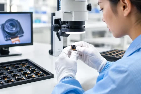
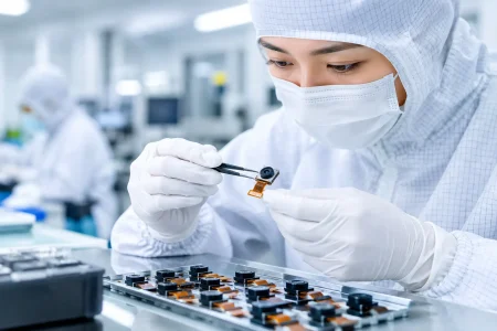
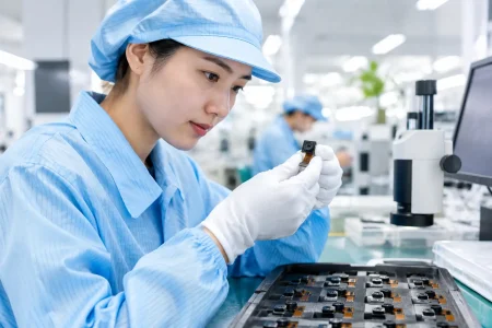
Production validation needs equal attention. Define golden samples, acceptance limits, focus inspection methods, electrical tests, cosmetic standards, and traceability requirements. At scale, consistency comes from controlled components and repeatable assembly processes, not from tuning each finished unit by hand.
Build for Supply Continuity and Customization
A design can be technically correct and still be difficult to manufacture if it depends on a single sensor, a special lens with long lead times, or a connector that has not been qualified for volume assembly. Where product lifecycle matters, assess alternate components, supplier capacity, revision control, and end-of-life risk during the architecture phase.
This is also where an experienced module manufacturer can shorten development time. SincereFirst supports standard and customized camera module development across MIPI, USB, FPC, DVP, medical, and endoscope applications, helping teams align sensor selection, optics, mechanical constraints, and production requirements before volume ramp.
The most effective next step is to create a one-page architecture brief with the scene, image decision, required performance, physical constraints, interface, processing target, and expected annual volume. That document gives R&D, procurement, and manufacturing teams a shared definition of success – and gives a camera supplier the information needed to propose a solution that can move from sample to stable production.