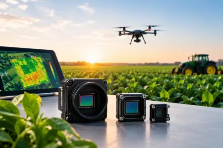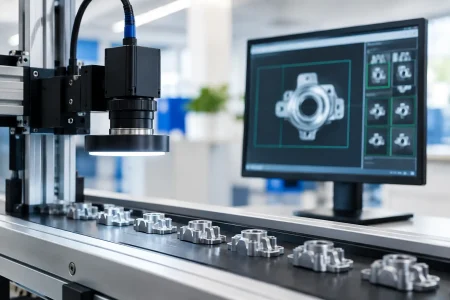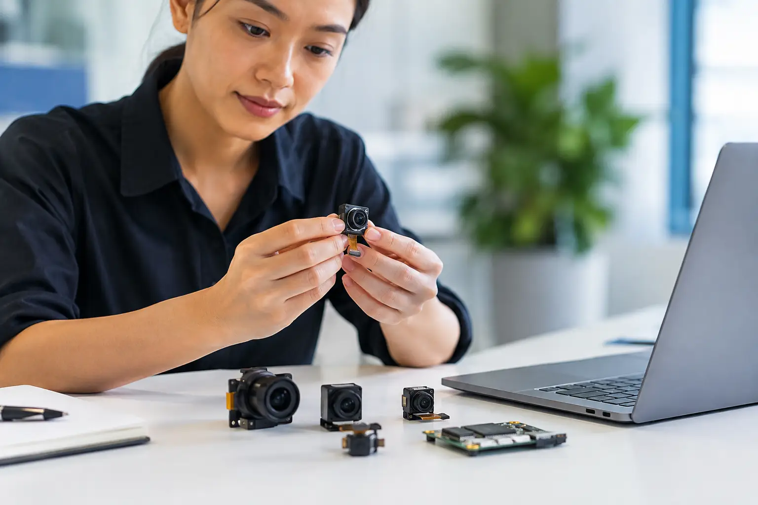
A camera module can look excellent in a lab demo and still create expensive problems at production scale. The difference usually is not resolution alone. It is whether the sensor, lens, interface, mechanical stack-up, image tuning, and supplier controls were specified for the actual device environment.
For OEMs, system integrators, and embedded teams, camera selection is an engineering decision with supply-chain consequences. A module must fit the available board space and power budget, work with the selected processor, deliver useful images under real illumination, and remain available through the product lifecycle. This guide explains how to specify a camera module around those requirements rather than choosing from a datasheet headline.
Start With the Imaging Task, Not the Resolution
The first question is what the camera must detect, measure, or record. A security terminal identifying faces at a doorway has different needs from a robotic arm locating parts, a handheld medical device viewing tissue, or an agricultural system classifying crop conditions.
Resolution matters only after the required field of view and smallest feature size are understood. If a system needs to inspect a 0.5 mm defect across a wide conveyor, the sensor must place enough pixels on that defect. Increasing resolution can help, but it also increases bandwidth, processing demand, storage requirements, and sometimes power consumption. A lower-resolution sensor with the correct lens and lighting may outperform a high-resolution module used without optical planning.
Define the working distance, target size, field of view, frame rate, lighting condition, acceptable motion blur, and image-quality criteria early. For machine vision, those criteria may include contrast at a specific spatial frequency, distortion limits, color fidelity, or repeatable exposure. For consumer and security products, low-light performance, HDR behavior, and face detail may carry more weight.
Specify the Camera Module Sensor for the Scene
The image sensor sets the baseline for sensitivity, dynamic range, shutter behavior, and pixel output. It should be chosen for the scene, not simply for its megapixel count.
CMOS sensors are the standard choice for most embedded applications because they offer compact integration, efficient power use, and high frame-rate options. Within that category, pixel size is a practical consideration. Larger pixels often collect more light and can improve low-light signal quality, but they require a larger optical format for equivalent resolution. Smaller pixels support compact, high-resolution designs, yet they can place stricter demands on illumination and lens quality.
Shutter type is equally consequential. Rolling shutter sensors expose rows sequentially. They are cost-effective and suitable for many static or moderately moving scenes, including access control, document capture, and general monitoring. Fast-moving objects or vibration can produce skew, wobble, or partial-image artifacts.
Global shutter sensors expose all pixels at the same time. They are often the better choice for industrial automation, robotics, barcode capture, and high-speed inspection. The trade-off can be higher cost, different low-light behavior, or fewer sensor choices at a given resolution. If the device will move, or if the subject moves quickly, test rolling versus global shutter under actual operating conditions before locking the design.
Interface Selection Determines Integration Effort
A camera module interface must match the host processor, cable length, bandwidth, and software environment. This decision affects more than electrical compatibility. It influences firmware work, mechanical layout, EMC performance, and production test methods.
MIPI CSI-2 for compact embedded designs
MIPI camera modules are common in smartphones, tablets, AI edge devices, robotics platforms, and compact custom hardware. MIPI CSI-2 provides high bandwidth through a small connector and flexible PCB assembly, making it well suited to space-constrained designs. Its limitation is integration complexity: the processor must support the selected sensor, lane configuration, timing, and driver stack. Cable length is also generally limited compared with USB.
USB for rapid deployment and broad compatibility
USB camera modules are attractive when the host needs plug-and-play operation or when engineering teams want to shorten software integration. UVC camera modules can operate with standard drivers on many operating systems, reducing development risk for kiosks, conferencing devices, diagnostic equipment, and PC-connected systems.
USB 2.0 is suitable for many HD imaging tasks, while USB 3.0 provides more bandwidth for higher resolution, higher frame rate, or lower-compression video. USB can simplify development, but the connector, cable routing, power delivery, and host-port availability still need consideration.
DVP for legacy and resource-conscious platforms
DVP camera modules remain useful in certain microcontroller and legacy embedded designs. The parallel interface can be straightforward where supported, but it uses more pins and does not scale as efficiently for high-bandwidth imaging. It is often a fit when the processor architecture is already established and the image requirement is modest.
Optics Are Part of the Camera Module Specification
A camera module is not only a sensor on a PCB. Lens selection determines whether the sensor can deliver useful image data. Focal length, field of view, aperture, distortion, depth of field, and focus method must be evaluated as a system.
A wide-angle lens covers more area but may introduce barrel distortion and reduce pixel density on the target. A narrow field of view improves detail at distance but can make alignment less forgiving. Fixed-focus optics work well where object distance is controlled, such as scanners, smart locks, or fixed industrial stations. Auto-focus can support variable working distances, although it adds mechanical complexity, power demand, startup time, and qualification considerations.
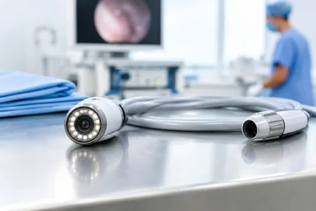
For inspection, medical, and measurement applications, lens distortion and focus consistency may matter more than visual attractiveness. For small-diameter endoscope modules, optical design becomes even more constrained. Diameter, illumination, viewing direction, cable construction, and depth of field must be considered together. A 0.9 mm endoscope module solves a very different problem from a board-level security camera, even if both use compact CMOS sensors.
Plan Image Tuning and Lighting Early
Raw sensor output is rarely the final image a product needs. Image signal processing controls demosaicing, white balance, noise reduction, sharpening, exposure, HDR behavior, and color reproduction. A default tuning profile can be acceptable for prototypes, but production devices often need tuning for their enclosure, illumination source, target material, and user expectations.
Lighting deserves the same attention as the sensor. Uncontrolled lighting is a common reason computer vision accuracy falls after deployment. Reflective metal, dark plastic, translucent packaging, and daylight changes can all challenge an otherwise capable camera. Ring lights, backlights, polarized illumination, infrared LEDs, and synchronized strobes may improve results more effectively than a sensor upgrade.
For color-critical work, specify the light source and reference targets used during evaluation. For near-infrared applications, confirm sensor response, IR-cut filter selection, illumination wavelength, and any required day-night switching. These details should be included in the camera module requirement document, not left to late-stage testing.
Design for Manufacturing, Not Just the First Sample
A sample proves potential. Production requires repeatability. When evaluating a camera module supplier, ask how sensor lots are controlled, how lenses are aligned, what image inspection is performed, and how traceability is maintained. Cleanroom assembly, defined test fixtures, optical alignment processes, and outgoing image validation are meaningful because small variations can affect focus, shading, dead pixels, and image uniformity.
Mechanical integration also deserves early review. Confirm module dimensions, FPC bend radius, connector type, mounting points, lens height, thermal path, and tolerance stack-up against the final enclosure. A lens that is lightly stressed by a housing or adhesive process can shift focus. A poorly supported flexible cable can fail after repeated motion. These are production issues, not minor mechanical details.
Customization should be purposeful. Common modifications include FPC length and pinout, connector selection, lens field of view, filter configuration, LED integration, housing design, and image tuning. The right supplier should help distinguish changes that add real product value from changes that add cost, lead time, and qualification risk.
SincereFirst supports both standard module supply and custom imaging development, allowing teams to move from early evaluation to scalable manufacturing without treating the camera as an isolated component.
Build a Requirement Package Before Requesting Samples
A clear requirement package accelerates quotation, sample selection, and engineering review. It should state the application, expected annual volume, target price range, preferred interface, host processor, resolution and frame-rate target, field of view, working distance, lighting conditions, operating temperature, module envelope, and compliance needs.
It should also identify which requirements are fixed and which remain open for engineering recommendations. For example, a product team may know it needs a 120-degree field of view and USB 3.0 output, while leaving sensor model and lens aperture open. That gives the manufacturer room to propose a design that balances performance, availability, and cost.
Validate Under Real Conditions
Before approving a design, test it in the final or near-final enclosure with representative software, cable routing, illumination, and motion. Evaluate more than center-image sharpness. Check edge performance, focus consistency, exposure stability, startup behavior, thermal drift, latency, frame drops, and image quality across multiple units.
When the application is safety-sensitive, medically oriented, or used for automated decisions, define acceptance criteria that can be measured repeatedly. A subjective statement such as “image looks clear” is not enough for supplier qualification. Measurable targets make production approval faster and future quality discussions more objective.
The best camera module is the one that gives your device dependable visual information every day, across real users, real lighting, and real production variation. Specify that outcome clearly, and the component choice becomes far more predictable.