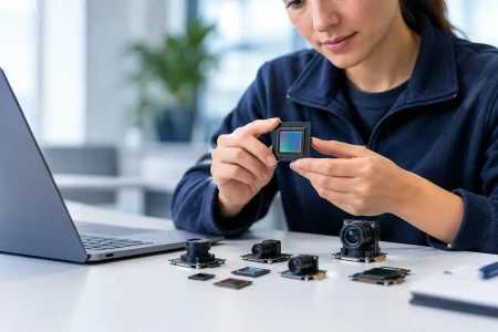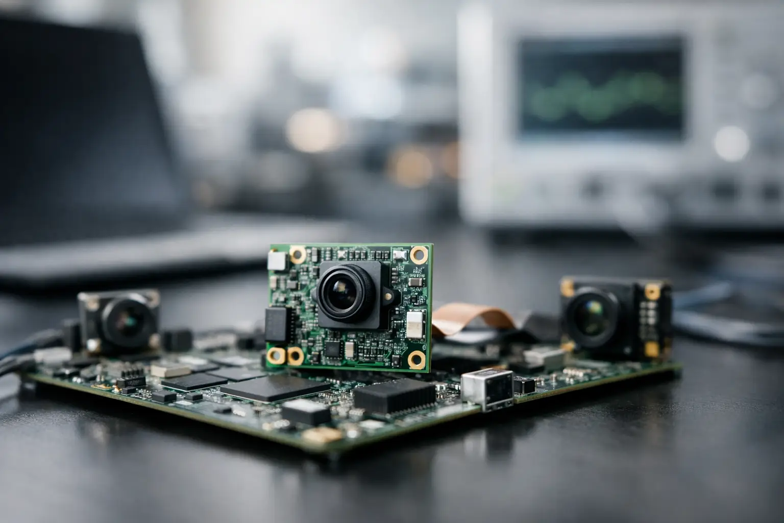
A camera specification can look excellent on a datasheet and still fail the product once it reaches a cramped enclosure, a low-power processor, or a factory line. Board level imaging solutions address that gap by bringing the sensor, lens, electronics, interface, and mechanical package together as an integration-ready camera assembly. For embedded product teams, the goal is not simply to source a camera. It is to build a dependable imaging function that can be qualified, manufactured, and supported over the life of the device.
What Board Level Imaging Solutions Deliver
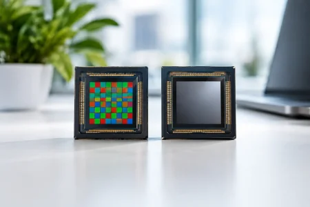
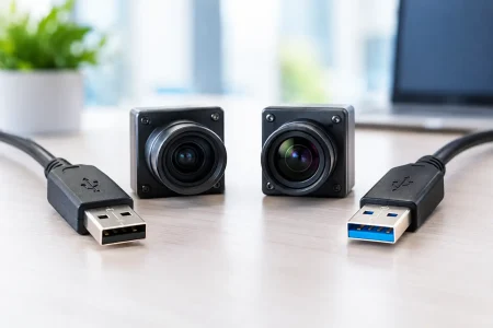
A board-level camera is an imaging module built around a printed circuit board rather than a finished consumer camera housing. It commonly includes a CMOS image sensor, lens holder and lens, power and clock circuitry, signal processing where required, and an output connector or cable. The module may connect through MIPI CSI-2, DVP, USB 2.0, USB 3.0, or another defined interface depending on the host platform.
This architecture gives OEMs more control over size, orientation, field of view, cable routing, and image behavior. It also removes work from the device development team. Instead of designing the complete camera electronics from the ground up, engineers begin with a tested optical and electrical subsystem that can be adapted to the application.
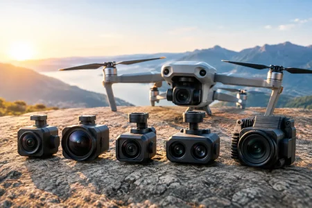
The right solution depends on the operating environment and the job the image must perform. A smart door station may prioritize low-light color performance and wide dynamic range. A warehouse robot may need low latency and stable exposure while moving. A medical or industrial inspection device may require a very small diameter module, controlled illumination, and consistent close-focus performance. Resolution alone does not resolve any of these requirements.
Start With the Image Requirement, Not the Sensor Name
Sensor selection is often the first discussion, but it should follow a clearer definition of what must be seen. Teams should establish the target object size, working distance, field of view, illumination conditions, acceptable motion blur, and detection or recording task. These factors determine the pixel density and optical design needed at the object plane.
For example, a 4K sensor is not automatically better than a 2MP sensor for machine vision. Higher resolution increases data volume, storage needs, processor demand, and potentially heat generation. If the host cannot process the additional data at the required frame rate, the higher-resolution module can reduce system performance rather than improve it.
Pixel size, sensor sensitivity, dynamic range, shutter type, and frame rate deserve the same attention as resolution. Global shutter sensors are generally preferred when fast motion must be captured without geometric distortion, such as conveyor inspection, robot guidance, and barcode reading. Rolling shutter sensors can be a cost-effective choice for static scenes, video communication, access control, and many general embedded applications.
Low-light performance also involves more than sensor sensitivity. Lens aperture, exposure strategy, illumination spectrum, image signal processor tuning, and noise reduction all affect usable image quality. A module selected for an outdoor security product should be assessed under bright backlight, nighttime illumination, and transitional lighting, not only under controlled office lighting.
Interface Selection Drives System Architecture
The camera interface determines how image data reaches the processor and how much integration work remains. It is a system decision, not a connector decision.
MIPI CSI-2 camera modules are often selected for compact embedded products using mobile-class application processors, single-board computers, and AI edge platforms. MIPI supports high-speed image transmission with a small physical footprint and low power consumption. Its trade-off is that host compatibility, lane configuration, timing, driver support, and flex cable design must be validated carefully.
USB camera modules offer a faster path for systems that require plug-and-play behavior. UVC-compliant modules can work with standard operating system camera frameworks, reducing driver development for many applications. USB 3.0 is a practical choice when higher resolution or frame rate requires more bandwidth than USB 2.0 can carry. The trade-off is typically larger connectors, greater cable constraints, and higher power consumption than a tightly integrated MIPI design.
DVP modules remain relevant for microcontroller-based products, legacy embedded platforms, and cost-sensitive systems with parallel camera interfaces. They can be straightforward to implement, but their bandwidth and routing requirements may limit higher-resolution or high-frame-rate designs.
A capable camera module supplier should review the processor, operating system, available interfaces, expected cable length, and software environment before finalizing the output format. Choosing a module first and checking host support later is a common cause of schedule slips.
Optics Define What the Sensor Can Actually See
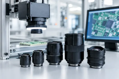
A high-quality sensor cannot compensate for an incorrect lens. Field of view must match the application area, while focal length, lens distortion, aperture, depth of field, and focus distance determine whether the critical detail is usable.
Wide-angle lenses are useful when a device must observe a large area from a short distance, including cabin monitoring, door access, indoor security, and service robotics. They also introduce distortion that may need calibration or software correction. A narrow field of view can provide more pixels on a distant target but becomes harder to aim and more sensitive to vibration or mechanical tolerance.
Fixed-focus modules are efficient for products with a known working distance. Auto-focus modules are better suited to variable-distance imaging, but they add mechanical complexity, power demand, control requirements, and qualification work. For close-range inspection, endoscope assemblies, and compact medical devices, lens selection must also account for the available barrel diameter, illumination placement, and heat management.
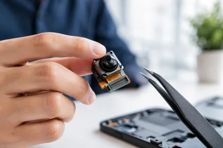
Mechanical design is equally important. The lens must hold focus through temperature change, vibration, shipment, and repeated use. The FPC cable bend radius, connector retention, module mounting points, and alignment of the camera to the product exterior should be reviewed before tooling is committed.
Build for Production, Not Only for the Prototype
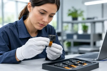
A sample that captures a good image is a starting point. Production-ready board level imaging solutions need controls that keep thousands of units consistent. That includes incoming component management, cleanroom assembly where needed, automated optical alignment, electrical testing, image inspection, and traceability for key materials.
The module should be tested against the conditions it will experience in the finished device. For industrial and outdoor products, this may include temperature cycling, vibration, drop resistance, cable flexing, humidity exposure, and extended operating time. For medical applications, material selection, image consistency, sterilization constraints, and applicable regulatory responsibilities require early engineering review.
Image tuning must also be repeatable. Exposure behavior, white balance, noise reduction, color response, and lens shading correction can differ across sensors and optical stacks. If the application uses computer vision algorithms, validation should measure algorithm output, not just images that look attractive to the human eye.
Early design reviews should cover four production questions:
- Can the module be assembled within the device tolerance stack?
- Is the selected sensor and lens combination available for the intended product lifetime?
- Can the host processor sustain the desired resolution and frame rate under full system load?
- Are test standards defined for both module acceptance and final-device image performance?
These questions are less glamorous than sensor comparison charts, but they protect the launch schedule and reduce field returns.
When Customization Creates Real Value
Standard modules are often the best choice when the enclosure, interface, optics, and operating conditions align with established designs. They shorten qualification time and support predictable sourcing. Custom development becomes justified when the camera must fit a nonstandard space, meet a specific optical target, integrate a specialized connector, support a unique cable length, or operate in difficult lighting or environmental conditions.
Common customization areas include sensor replacement, lens and field-of-view selection, FPC shape and length, board dimensions, connector orientation, LED integration, housing design, and image parameter tuning. The best custom program defines which items are truly fixed and which can remain flexible. Over-customization can increase nonrecurring engineering cost, extend validation, and make future component substitutions more difficult.
SincereFirst supports this process with standard camera module supply and tailored development across MIPI, DVP, USB, FPC, medical, and endoscope imaging platforms. For buyers, the practical advantage of working with an engineering-led manufacturer is faster feedback on whether a requested design can be produced consistently at volume, rather than merely demonstrated as a one-off sample.
Qualifying a Long-Term Imaging Partner
Camera sourcing should be evaluated as a supply and engineering relationship. Ask how optical alignment is controlled, how image quality is inspected, what traceability is retained, and how component changes are managed. Review prototype lead time, production capacity, failure-analysis support, and the process for approving a revised sensor, lens, or connector.
It is also useful to request representative images or test data from conditions close to the final application. A module intended for license plate capture, crop analysis, surgical visualization, or automated inspection should be evaluated against that task. Generic indoor test images do not prove field performance.
The strongest board-level camera design is the one that makes the finished product easier to build and more reliable to use. Define the image task precisely, select the interface and optics around the host system, and require manufacturing evidence before the design is locked. That discipline turns a camera module from a purchased component into an intelligent eye built for the product it serves.