
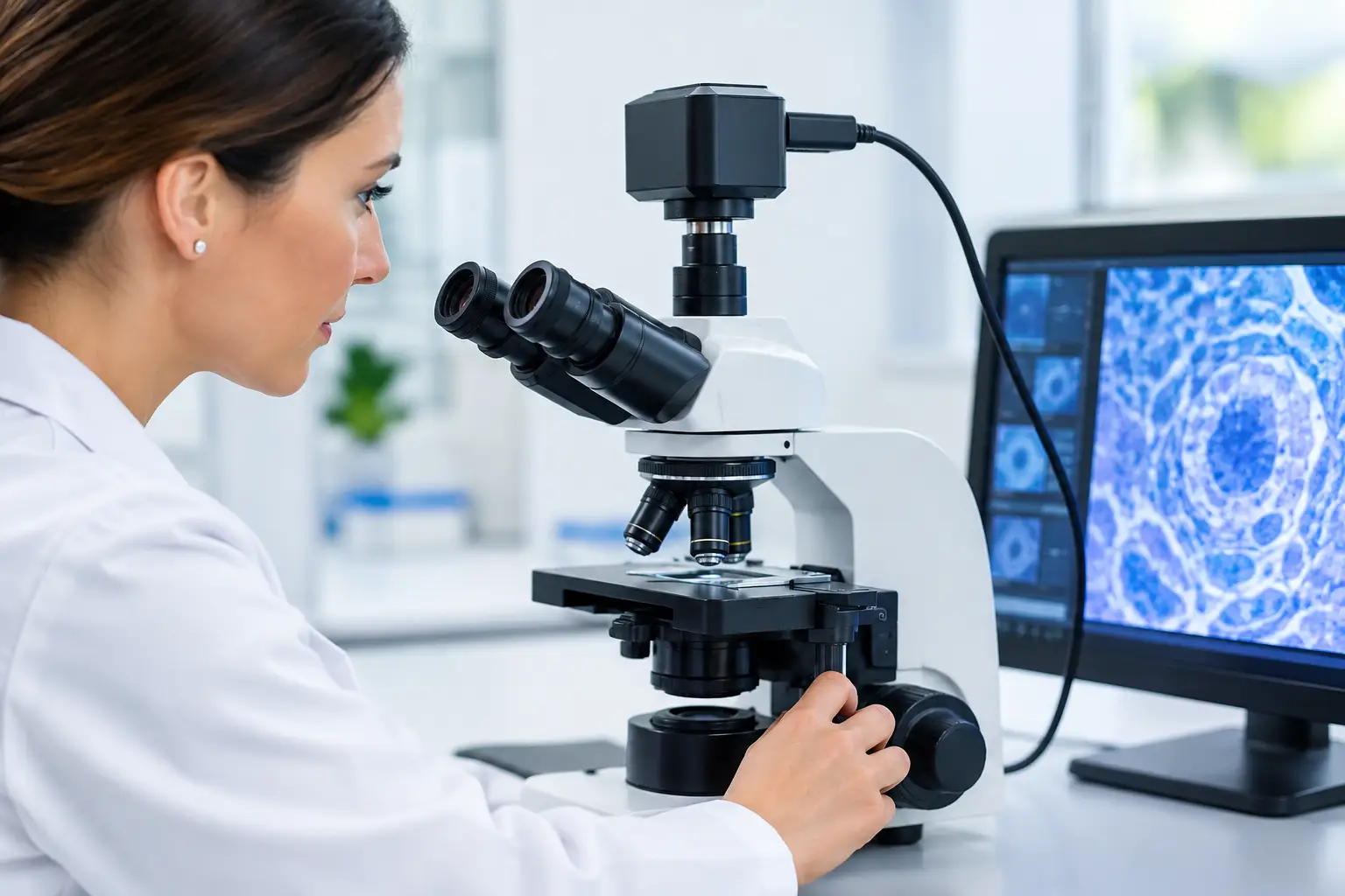
A microscopy camera can deliver impressive specifications on paper and still produce unusable results inside a finished instrument. Poor color consistency, uneven field illumination, dropped frames, focus shifts, or a sensor that physically does not fit the optical path can delay a program long after the camera selection appears complete. Effective microscopy camera integration is an engineering task across optics, electronics, mechanics, firmware, and manufacturing.
For OEMs building laboratory analyzers, digital microscopes, inspection equipment, and medical imaging devices, the objective is not simply to capture an image. It is to generate repeatable, application-relevant image data at the required speed, under controlled conditions, across every unit produced.
Start With the Imaging Requirement, Not the Camera
Camera selection should follow a defined imaging target. Begin with the specimen type, magnification range, field of view, contrast method, required measurement accuracy, capture rate, and operating environment. A brightfield educational microscope, a fluorescence instrument, and an automated semiconductor inspection system may all use a microscope objective, but their camera requirements are fundamentally different.
Resolution is often over-specified. More pixels only add value when the optical system can resolve corresponding detail and the host processor can move, store, and analyze the additional data. If pixel size is too small for the objective and tube lens combination, the system may gain file size and noise without gaining useful sample detail. Conversely, a larger sensor can preserve a wider field of view, which may be more valuable for screening, tile reduction, or operator workflow.
Frame rate must also be evaluated at the actual output format, bit depth, and exposure setting. A quoted maximum frame rate may apply only to a cropped mode or reduced resolution. For motorized stages and live inspection, exposure time, sensor readout, transfer bandwidth, and host-side processing all affect whether motion remains sharp and responsive.
Match Sensor Format to the Optical Path
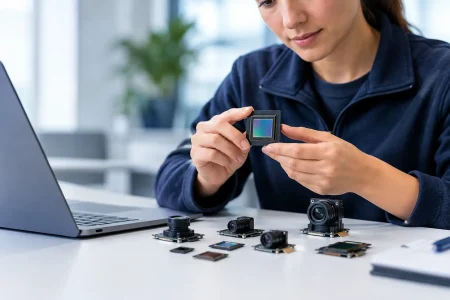
The sensor and microscope optics must be treated as one imaging chain. The objective creates the image, while the tube lens, relay optics, C-mount adapter, and camera sensor determine how much of that image is captured and how well it is sampled.
A sensor that is larger than the corrected image circle can show dark corners, loss of sharpness near the edge, or mechanical vignetting. A sensor that is too small may waste available field of view. The target is a sensor format that fits the usable optical field while meeting the required spatial sampling.
Pixel size matters as much as resolution. Small pixels can capture fine detail when supported by the numerical aperture and magnification of the optical system. They can also reduce full-well capacity and demand stronger illumination. Larger pixels generally offer better light collection and may improve performance in low-light microscopy, especially where exposure time must remain short.
For color imaging, evaluate the sensor’s color filter response under the actual illuminant. White balance set under a cool LED source may not hold under a halogen source or a multi-channel illumination design. In analytical instruments, automatic color adjustment can create variation between images. Fixed calibration settings, controlled illumination, and reference targets are usually better choices when consistent color is part of the product requirement.
Choose an Interface That Supports the Full Data Path
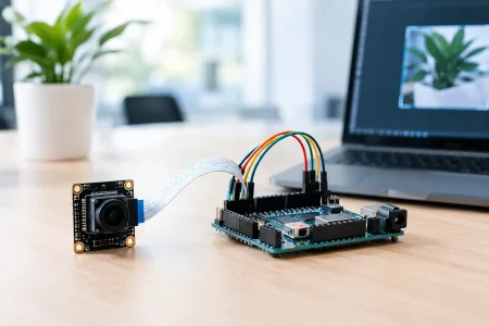
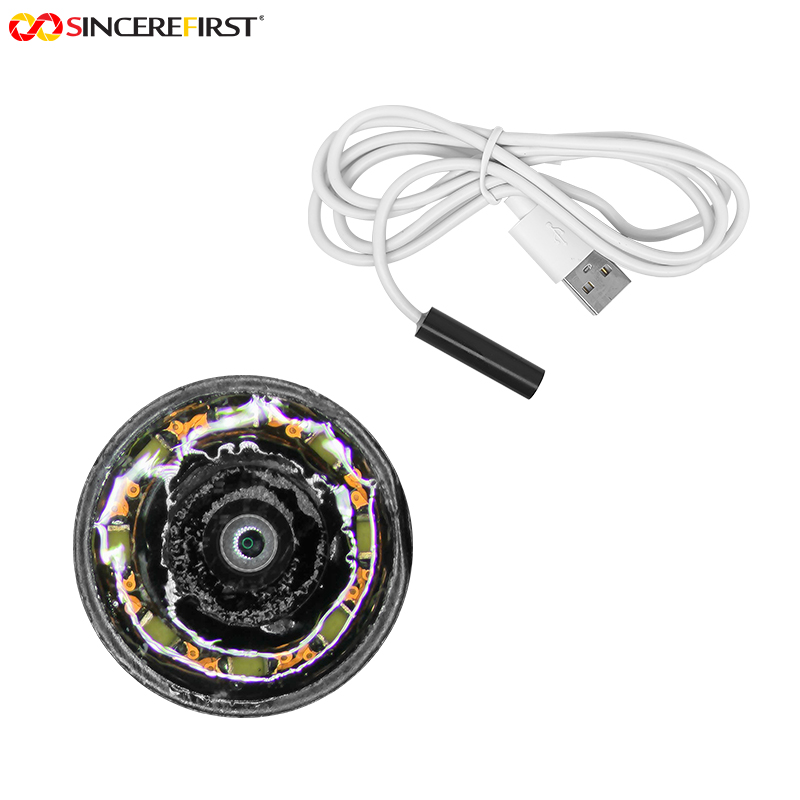
The camera interface affects enclosure design, cable routing, power delivery, software architecture, and production testing. USB 2.0 camera modules can be economical for moderate-resolution still capture or basic live viewing. USB 3.0 provides significantly more bandwidth for high-resolution live imaging and faster frame rates. UVC support can reduce driver complexity for standard video applications, although proprietary controls may still be necessary for exposure, gain, triggering, and calibration.
MIPI CSI-2 is a practical choice for compact embedded instruments built around supported processors or system-on-chip platforms. It offers low-latency transfer and a small interconnect footprint, but integration depends on compatible lanes, board layout, device-tree configuration, image signal processor support, and software resources. DVP can suit legacy or lower-bandwidth embedded platforms, while specialized industrial architectures may require different transfer methods based on distance, synchronization, or deterministic timing needs.
Do not evaluate interface bandwidth in isolation. Calculate the uncompressed payload using resolution, frame rate, pixel format, and bit depth. Then account for protocol overhead and the processing headroom needed for image enhancement, compression, display, storage, or AI analysis. A camera that works during a brief engineering demonstration can fail under continuous operation if thermal load or data buffering was not considered.
Control Illumination Before Tuning Image Processing
Many perceived camera defects are actually illumination problems. Uneven lighting can mimic sensor shading. Inadequate intensity can force high gain, raising visible noise. LED flicker can create frame-to-frame variation, particularly when exposure is not synchronized to the illumination driver.
Microscopy instruments should define illumination geometry early. Transmitted brightfield, coaxial reflected light, ring illumination, darkfield, polarized light, and fluorescence each impose different demands on exposure control and optical filtering. The camera should support the required dynamic range without clipping highlights or losing shadow detail in the features that matter to the measurement.
For fluorescence and other low-signal applications, sensitivity, read noise, dark current, cooling strategy, and long-exposure behavior deserve close attention. A highly sensitive sensor may be the right choice, but it can also expose stray light, filter leakage, or mechanical instability that was not visible in a conventional brightfield setup. Performance should be characterized at realistic signal levels rather than under ideal bench lighting.
Mechanical and Thermal Design Determine Long-Term Stability
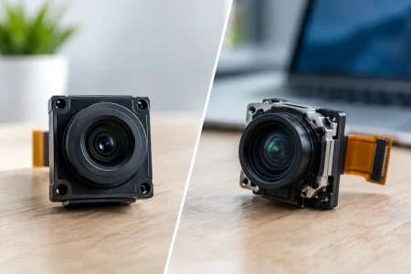
A camera module is not interchangeable with a finished camera assembly. In compact microscopy products, board dimensions, connector location, lens mount alignment, heat dissipation, and cable strain relief directly affect yield and image quality.
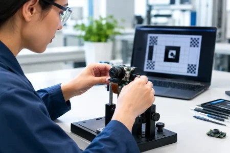
Mechanical tolerances between the sensor plane and optical axis are especially critical. Tilt can cause one side of the image to fall out of focus, while sensor position error can change the magnification or prevent the instrument from reaching focus. Fixed-focus relay optics and high-magnification systems leave little room for adjustment.
Thermal design also deserves early attention. Sensors, image signal processors, and high-speed interfaces generate heat during continuous operation. Rising temperature can increase noise, change black level, affect color behavior, and shorten component life. Heat paths, enclosure materials, ventilation limits, and ambient operating conditions should be validated using production-representative hardware, not an open bench setup.
Build Calibration Into the Product Architecture
Calibration is not a final factory step. It should be designed into the hardware and firmware from the beginning. The specific method depends on the application, but microscopy systems commonly need black-level correction, lens shading correction, white balance control, pixel-defect handling, geometric calibration, and scale verification.
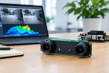
If images support measurement, traceability is central. Pixel-to-micron conversion can vary with objective selection, zoom position, sensor placement, and digital scaling. Store calibration data in a controlled format and define when it must be renewed. For multi-camera systems, synchronization and camera-to-camera variation must be managed as part of the same process.
A practical production validation plan should cover at least these five areas:
- Optical performance across the center and edges of the field of view
- Exposure, color, and noise stability under defined illumination
- Frame rate and data integrity during sustained capture
- Trigger timing or synchronization where motion is involved
- Thermal behavior after extended operation in the intended enclosure
Acceptance criteria should be numerical wherever possible. Terms such as “clear image” or “good color” are difficult to reproduce across suppliers, factories, and service teams. Define measurable limits for uniformity, sharpness, signal-to-noise ratio, frame loss, focus position, and color deviation.
Plan for Manufacturing Before the Prototype Is Approved
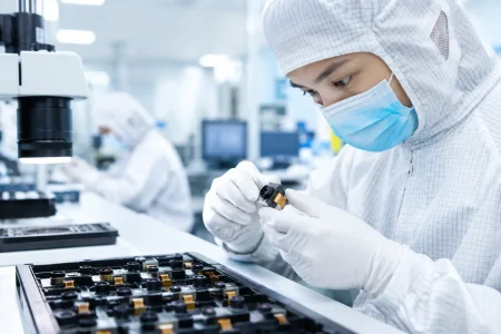
A successful prototype does not automatically become a manufacturable imaging product. Component availability, sensor lifecycle, connector mating reliability, board-level test access, module alignment procedures, and calibration cycle time all affect scale-up risk.
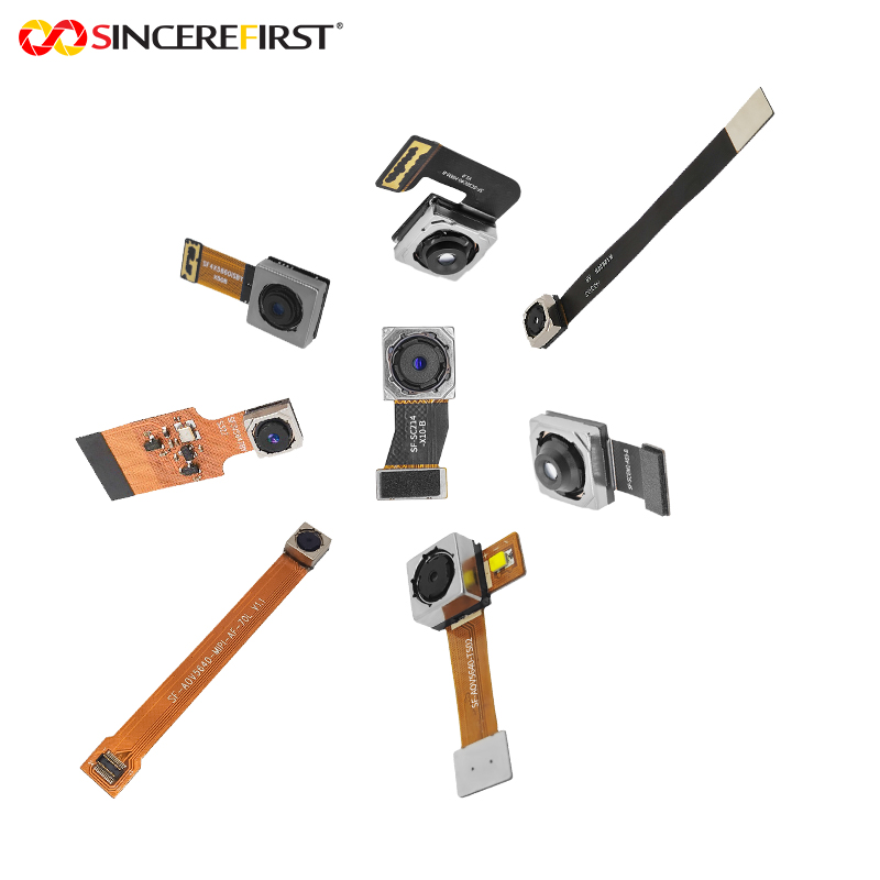
This is where an experienced camera module manufacturer contributes beyond supplying a sensor board. SincereFirst supports OEM programs with standard USB, MIPI, DVP, and custom camera module options, then aligns optical, electrical, and mechanical details with the instrument architecture. Fast samples are useful, but the larger value is a defined path from proof of concept to stable volume production.
Customization should be purposeful. A custom FPC length, connector orientation, lens stack, infrared filter, board outline, or firmware control can simplify the final device and reduce assembly risk. However, each change can affect validation time, tooling, minimum order planning, and future serviceability. The right design balances differentiation with supply continuity.
Treat Microscopy Camera Integration as a System Decision
The best microscopy camera is the one that meets the image requirement inside the complete instrument, repeatedly and at production scale. That decision comes from aligning optical performance, interface bandwidth, illumination control, mechanical tolerance, thermal behavior, and calibration strategy before the design is frozen.
When those disciplines are addressed together, the camera becomes more than a component. It becomes a dependable imaging foundation for instruments that must perform accurately long after the first sample image is approved.