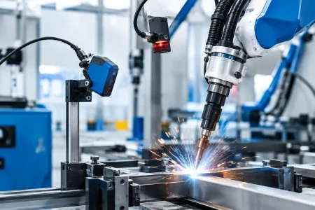

A vision system can pass a lab demonstration and still fail on the production floor. Glare changes with a shift in lighting, vibration moves a lens by a fraction of a millimeter, a long cable introduces errors, or a replacement camera module performs differently from the approved sample. Industrial imaging is the engineering discipline of preventing those small variations from becoming costly inspection errors, machine downtime, or field returns.
For OEMs, automation builders, and system integrators, the camera is only one part of the decision. A deployable imaging system must produce useful image data under defined operating conditions, connect reliably to the host platform, fit mechanical constraints, and remain manufacturable at volume. The right specification is not necessarily the highest resolution or fastest interface. It is the combination that makes a measurement, classification, guidance, or documentation task repeatable.
Industrial Imaging Starts With the Decision
The first question should be: what must the system decide from an image? “Detect defects” is not enough. A practical requirement identifies the feature to be seen, its smallest relevant size, its contrast against the background, the allowable false-pass and false-reject rate, the distance to the object, and the required inspection cycle time.
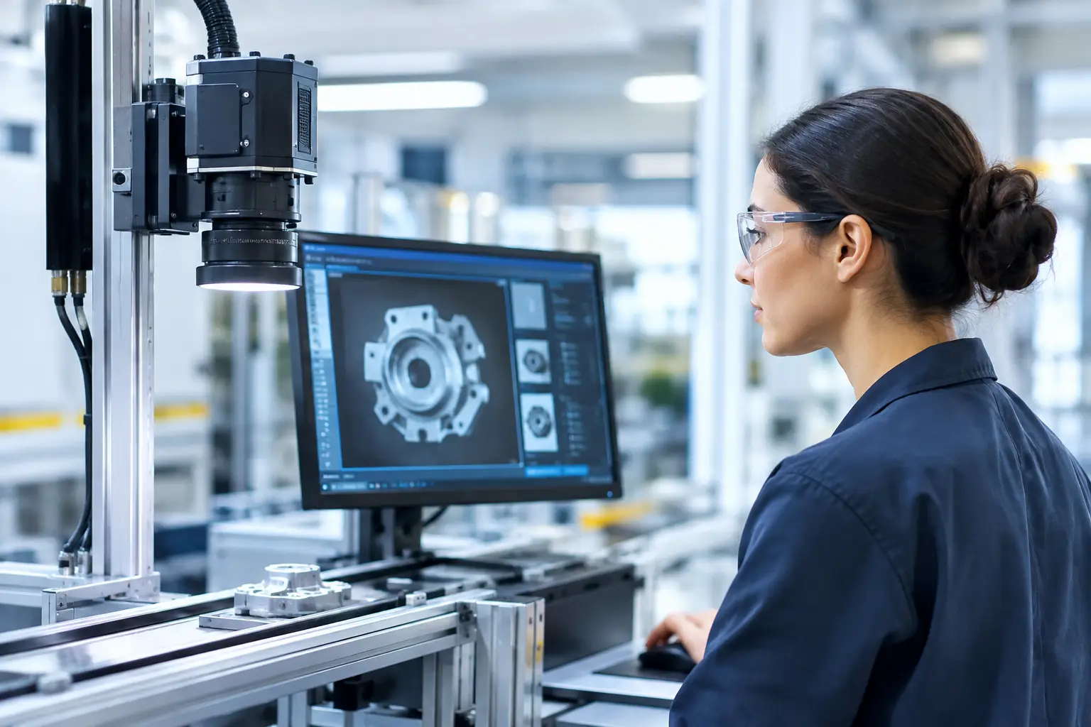
Consider a packaging line verifying date codes. The task may require readable characters at a specific line speed, despite reflective film and changing package positions. A robot picking components has a different need: it may require low-latency positional data and controlled depth of field. A bore inspection device prioritizes a compact optical path, illumination placement, and detail at close range. These applications may all use digital cameras, but they do not call for the same sensor, lens, illumination, or data interface.
Defining the decision early prevents a common mistake: selecting a high-resolution module first, then discovering that motion blur, poor lighting, or processor bandwidth limits the actual result. More pixels can improve spatial detail, but they also increase data load, storage requirements, heat, processing time, and cost. If the defect is large and contrast is controlled, a lower-resolution sensor with a better optical and lighting design can be the more capable production solution.
The Imaging Chain Is Only as Strong as Its Weakest Part
An industrial image is created by a chain of components and conditions. Each must support the required result. Sensor selection matters, but it cannot compensate for a lens that does not resolve the target detail or lighting that hides the feature being inspected.
Sensor and shutter selection
Sensor size, pixel size, sensitivity, dynamic range, and frame rate affect what data reaches the processor. Small pixels can support high resolution in compact modules, while larger pixels can offer advantages in low-light conditions. Neither choice is universally better. The working distance, field of view, illumination budget, and target contrast determine the appropriate balance.
Shutter type is equally important for moving scenes. A rolling shutter can be efficient and suitable for many stationary or controlled applications. However, fast conveyor motion, rapid robot movement, or vibration can create geometric distortion when rows of pixels are exposed at different times. A global shutter captures the frame simultaneously and is often the better choice where accurate position or shape matters during motion. The trade-off may include sensor availability, cost, resolution options, and low-light performance.
Optics and illumination
Optics convert an application requirement into usable pixels. Focal length defines the field of view at a given working distance, while aperture influences light collection and depth of field. A wide aperture can improve exposure in low light, but it can reduce the range that remains in focus. Stopping down increases depth of field, yet requires more illumination or longer exposure.
Illumination deserves the same engineering attention as the camera. Backlighting can reveal silhouettes and edge defects. Low-angle lighting can make scratches, embossing, or surface texture visible. Diffuse lighting can reduce glare on reflective materials. Near-infrared illumination can help separate features that have limited visible-light contrast. The best lighting geometry depends on the defect and material, not on a generic preference for bright light.
For compact equipment, integrated LEDs may reduce assembly complexity. For high-precision inspection, external lighting with controlled geometry and triggering may offer better consistency. In either case, thermal behavior, LED aging, cable routing, and service access should be considered before design release.
Interface and processing architecture
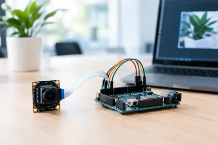
The selected interface must match the host architecture and intended data path. MIPI CSI-2 is widely used in embedded devices where compact size and direct processor connectivity are priorities. USB camera modules, including USB 2.0, USB 3.0, and UVC options, can shorten integration time for PCs, industrial controllers, and systems requiring plug-and-play behavior. DVP remains relevant for certain legacy or resource-constrained platforms.
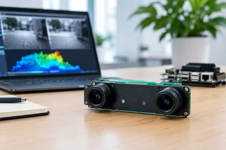
Bandwidth calculations should use actual image format, frame rate, and overhead rather than nominal interface speed alone. A system that operates correctly with an uncompressed test stream may fail once it adds image processing, recording, multiple cameras, or network transmission. Triggering, synchronization, exposure control, and timestamping also need defined ownership between the camera, host, and automation controller.
Designing for Production, Not Just Proof of Concept
A module that works on an evaluation board is not automatically ready for volume deployment. Production-grade industrial imaging requires control of mechanical tolerances, component changes, optical alignment, firmware configuration, and test criteria.
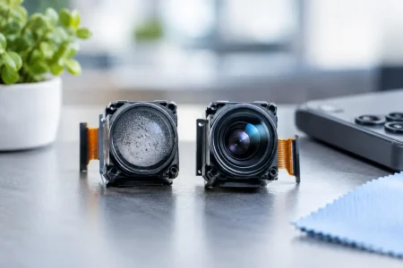
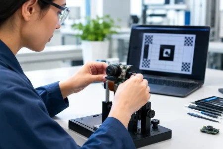
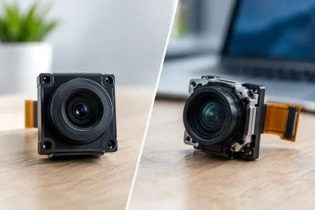
Camera modules are particularly sensitive to stack-up variation. Lens position, sensor tilt, adhesive cure behavior, connector retention, and flex routing can affect focus, image uniformity, or long-term reliability. When a product has a tight depth envelope or a nonstandard viewing angle, custom mechanical and optical integration should begin before the enclosure is finalized. Late changes are expensive because they can require revisions across the camera, housing, cable, thermal design, and image-processing algorithm.
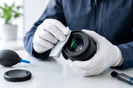
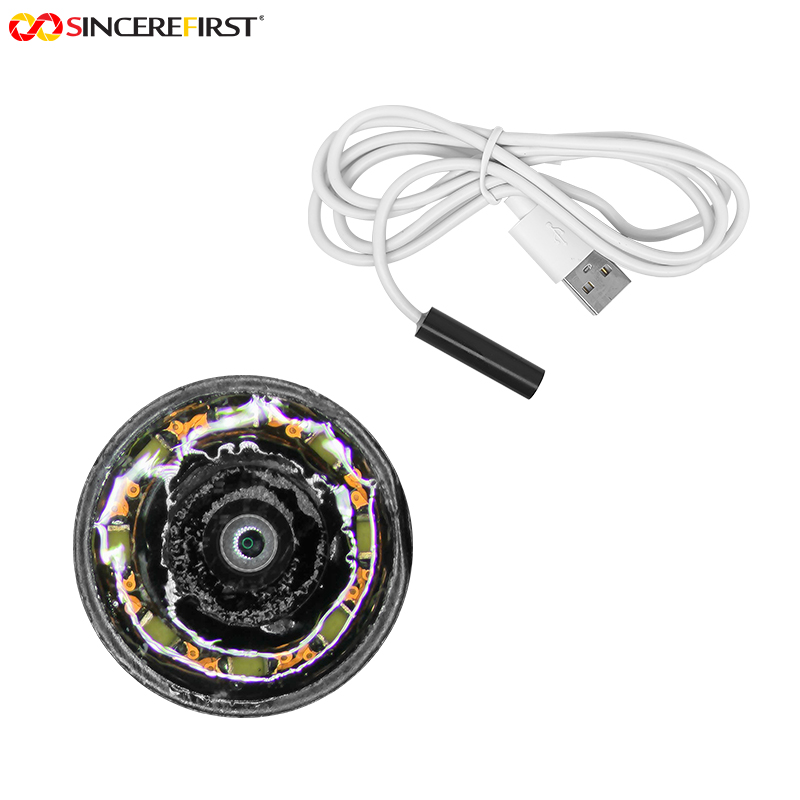
Environmental requirements also change the solution. A module placed inside a protected cabinet has different needs than one exposed to dust, washdown, temperature cycling, vibration, or electromagnetic noise. Protective windows can introduce reflections or reduce image contrast. Long flex cables can create signal-integrity challenges. In medical and industrial endoscope applications, small diameter, illumination, heat management, and sterilization or cleaning methods add further constraints.
A supplier qualification process should examine more than sample image quality. Business buyers should verify the supplier’s ability to control revision changes, document specifications, perform incoming and outgoing inspection, maintain traceability where required, and support a clear transition from prototype to mass production. Fast samples are valuable, but repeatable production is the larger commercial risk to manage.
A Practical Selection Framework for Industrial Imaging
Before requesting samples, prepare a short application brief that gives engineering teams enough information to make informed trade-offs. It should cover these five areas:
- The target feature, minimum size, material, contrast, and acceptable inspection error rate.
- Working distance, field of view, object motion, required frame rate, and available mounting space.
- Lighting conditions, including ambient light, reflective surfaces, and whether external illumination is possible.
- Host processor, operating system, preferred interface, power limits, cable length, and software requirements.
- Expected annual volume, environmental conditions, certification needs, target cost, and development schedule.
This information enables a supplier to recommend a standard module where it is sufficient, rather than forcing unnecessary customization. It also identifies cases where a tailored lens holder, FPC length, connector orientation, sensor tuning, or illumination arrangement will reduce total project risk.
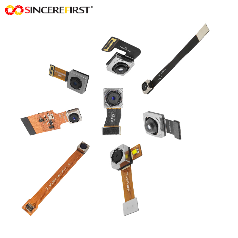
SincereFirst supports this path with embedded camera modules and customized imaging development for industrial automation, robotics, medical devices, agriculture, security, and smart equipment. The practical advantage of working with an experienced manufacturer is not simply access to more module types. It is the ability to evaluate optics, electronics, mechanical integration, and volume production as one connected engineering problem.
Validation Should Reproduce Real Operating Conditions
Image validation should occur under the conditions that matter, not only under ideal bench lighting. Test the full range of object position, speed, surface finish, temperature, illumination drift, and expected contamination. If an algorithm depends on a threshold, check how much margin remains when exposure shifts or the lens becomes slightly dirty. If a camera will operate continuously, validate heat rise and image stability over time.
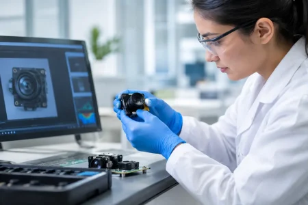
Golden samples and measurable acceptance criteria are useful at this stage. Define what constitutes acceptable focus, dead-pixel behavior, color response when color is relevant, frame stability, and connector performance. For inspection systems, retain representative pass and fail samples so software and hardware changes can be checked against the same dataset.
The goal is not to eliminate every variable. It is to understand which variables affect the decision and design enough margin around them. That discipline turns image capture into dependable machine data, which is the real value of industrial imaging.
When evaluating a camera module, ask whether the proposed solution will still deliver the required image after thousands of operating hours, across normal production variation, and at the volumes your product requires. That question usually leads to a better design than comparing specifications alone.