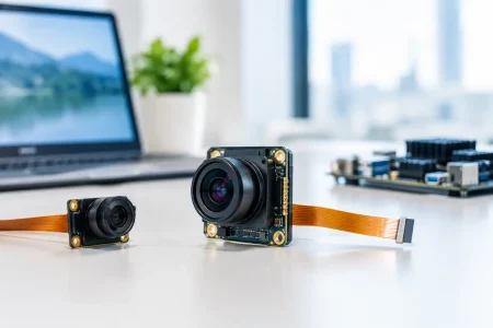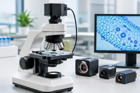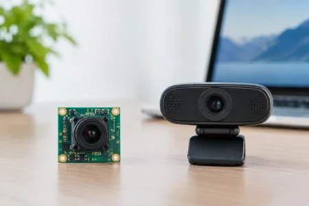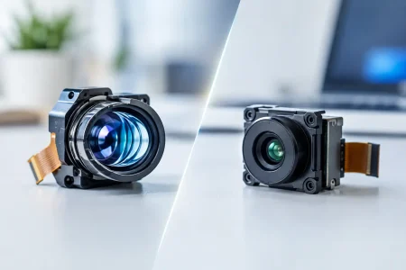

A camera module can produce a sharp, well-exposed image and still fail a machine vision task if straight edges bend, dimensions shift near the frame boundary, or feature locations move with lens position. Optical distortion correction addresses these errors before they become rejected parts, inaccurate measurements, or unreliable detection results. For embedded imaging teams, the goal is not merely a more natural-looking image. It is repeatable geometry that supports the intended application.
In compact camera designs, distortion is often the price of a wider field of view, shorter working distance, or lower module height. That trade-off can be entirely acceptable when it is modeled early, calibrated correctly, and supported by the sensor, lens, processor, and mechanical design. When it is ignored until late-stage integration, correction can add latency, crop useful pixels, and complicate system validation.
What Causes Optical Distortion in Camera Modules?
Optical distortion occurs when an imaging lens does not map a real-world straight line to a straight line on the sensor plane. It is different from blur, noise, chromatic aberration, and perspective. Those effects may appear in the same image, but each requires a different engineering response.
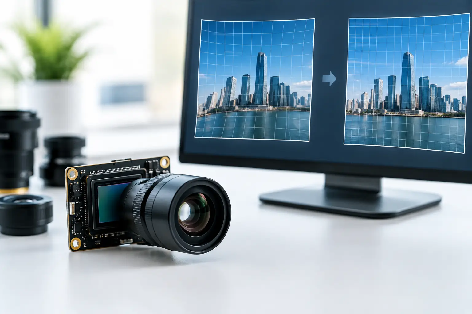
Barrel distortion is common in wide-angle lenses. Lines near the edge of the image curve outward, creating a bulging appearance. Pincushion distortion has the opposite effect, with lines bending inward. More complex lenses may show mustache distortion, where the distortion changes direction between the center and outer regions of the frame.
For a consumer video camera, moderate distortion may be corrected mainly for visual quality. For an industrial inspection system, agricultural guidance camera, robot navigation platform, or medical imaging device, the same distortion can change the reported position or size of an object. A few pixels of uncorrected displacement may be insignificant in a monitoring feed but unacceptable when locating a connector pin, verifying a package label, or reconstructing a surface.
The actual distortion profile depends on several factors: lens design, focal length, field of view, sensor format, lens-to-sensor alignment, focus setting, working distance, and assembly tolerance. This is why a generic correction table is rarely sufficient for a customized imaging product.
Optical Distortion Correction Starts With System Requirements
The right correction approach depends on what the camera must deliver. R&D teams should define geometric performance alongside traditional specifications such as resolution, frame rate, interface, power consumption, and module dimensions.
For example, an autonomous mobile robot may need a wide field of view to detect obstacles in close proximity. Barrel distortion can be managed if the corrected output preserves reliable spatial relationships in the region used for navigation. A metrology camera may prioritize low-distortion optics from the start because aggressive software correction reduces the usable field of view and can lower effective edge resolution.
Key requirements should include the allowable residual distortion, the usable corrected image area, target working distance, calibration distance range, required measurement accuracy, and acceptable processing latency. Teams should also identify whether the output is intended for human viewing, machine analysis, or both. A security camera can tolerate different compromises than a camera module used for automated optical inspection.
Lens Selection Reduces the Burden on Software
Software correction is powerful, but it does not replace appropriate optics. A very wide-angle lens can capture more scene information in a compact assembly, yet it may require stronger remapping. During remapping, pixels are interpolated into new positions. This may soften fine detail, especially toward the edges, and the corrected frame is often cropped.
Selecting a lens with lower native distortion can reduce those effects. The compromise is usually a larger lens, narrower field of view, higher optical cost, or a different working-distance requirement. There is no universal best choice. The correct design is the one that meets the application’s field coverage and accuracy requirements with a practical manufacturing tolerance.
For endoscope modules, the constraint is even tighter. Small diameters demand compact optics, and a broad viewing angle is frequently necessary to inspect confined spaces. In these designs, distortion must be evaluated together with illumination, depth of field, sensor sensitivity, and the intended visual interpretation by the operator or software algorithm.
How Software-Based Correction Works
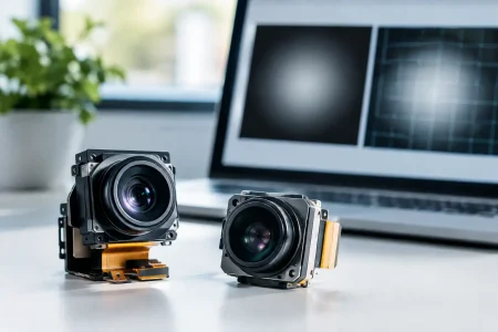
Most digital correction systems use a calibrated lens model to remap each output pixel to a location in the original captured frame. The calibration process identifies intrinsic camera parameters, including focal length, principal point, and distortion coefficients. The system then generates a correction map, sometimes called a lookup table or warp map.
During operation, the image signal processor, host CPU, GPU, FPGA, or dedicated vision processor applies that map. The best processing location depends on the platform. An ISP-based implementation can reduce host loading and simplify delivery of a corrected video stream. Host-side correction provides flexibility when algorithms, operating conditions, or output formats may change. FPGA processing can be suitable for deterministic, low-latency industrial systems.
Correction consumes compute resources and memory bandwidth. It can also introduce a frame of latency in some pipelines. For USB camera modules used with a PC-based application, host processing may be practical. For a MIPI camera module in a battery-powered smart device, on-chip or ISP-supported correction may be preferable. The interface alone does not determine the answer, but it strongly influences architecture decisions.
Calibration Must Match the Production Configuration
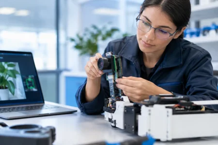
A correction profile is only accurate when it represents the camera as built. Changing the lens, sensor format, lens holder, focus position, or module mounting relationship can change the geometry enough to require recalibration.
A controlled calibration procedure typically captures a known target across the usable field of view. The calibration software identifies reference points, fits a lens model, calculates residual error, and produces parameters for correction. High-accuracy applications may also validate the corrected output at multiple working distances and temperatures.
The appropriate calibration level depends on the use case. Module-level calibration may be adequate for applications with moderate geometric requirements and tightly controlled assembly. Per-unit calibration can improve accuracy where lens placement variation matters, though it adds manufacturing time, fixture design, data traceability, and quality-control requirements. For high-volume programs, this decision should be made early because calibration needs to fit the production flow, not become a manual bottleneck after ramp-up.
Correcting Distortion Without Losing Useful Performance
A corrected image is not automatically a better image. Teams should assess its impact on the full imaging chain.
First, inspect the corrected field of view. Since edge pixels are shifted during remapping, blank areas may appear at the borders. These must be cropped or filled, which reduces the available image area. If the original camera was selected with little field-of-view margin, the corrected output may no longer cover the required inspection zone.
Second, measure detail after interpolation. Correction can alter modulation transfer performance and introduce small spatial variations. This is especially relevant for barcode reading, edge measurement, text recognition, and defect inspection. Testing should use representative targets at the actual working distance, not only a distortion chart.
Third, validate timing. A correction algorithm that performs well in an offline test may not meet a live 60 fps control loop. Latency, frame-to-frame consistency, processor temperature, and memory utilization all deserve measurement under peak operating conditions.
Finally, account for mechanical variation. A lens that shifts slightly during shock, vibration, or thermal cycling can invalidate a tightly tuned calibration. Mechanical retention, adhesive selection, lens holder tolerances, and assembly inspection are part of optical performance, not separate concerns.
A Practical Specification for OEM Camera Projects
When sourcing a camera module or custom vision solution, buyers should avoid requesting only a wide-angle lens with distortion correction. That description leaves too much open to interpretation. A usable specification identifies the sensor and resolution, lens field of view, target working distance, maximum raw and corrected distortion, corrected output resolution, crop allowance, frame rate, interface, processing location, calibration method, and acceptance criteria.
It should also define how performance will be tested. A percentage distortion figure by itself may not prove measurement suitability. For precision applications, specify residual pixel error or real-world dimensional error across named regions of interest. For a robot, define positional accuracy where navigation decisions occur. For an inspection camera, define the smallest feature that must remain detectable after correction.
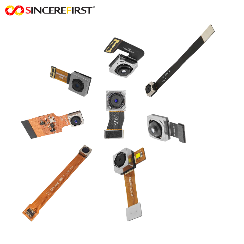
SincereFirst supports this type of engineering discussion through camera module selection, optical component matching, interface integration, and custom OEM/ODM development. The most efficient projects bring application constraints forward early, before enclosure dimensions and processing architecture become fixed.
When Correction Is Not the Right Answer
There are cases where the best decision is to reduce distortion optically rather than correct it digitally. This is often true in high-precision measurement, where every interpolation artifact matters, or where compute power is strictly limited. It can also be the better choice when the required corrected crop would remove too much of the scene.
Conversely, digital correction is highly effective when a wide field of view is necessary, image processing resources are available, and calibrated geometry matters more than preserving every raw edge pixel. The correct balance comes from testing the assembled camera in the real operating geometry, not from lens data alone.
A well-designed imaging system treats distortion as a measurable design parameter. Define the geometry your application needs, select optics and calibration accordingly, then verify performance on production-representative hardware. That discipline turns a camera module from a component that captures images into an intelligent eye that can support dependable decisions.