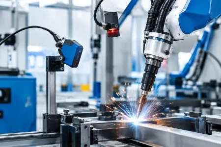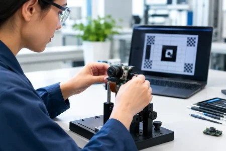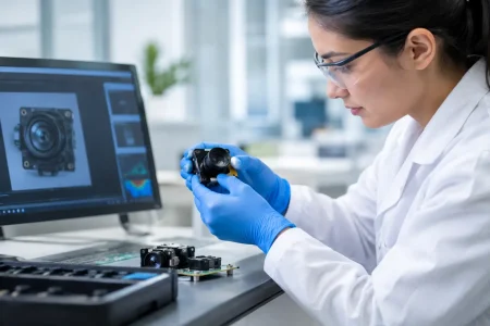

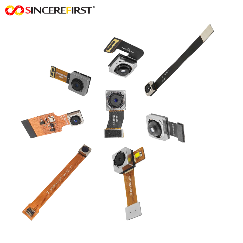
A camera that produces clear images on a laboratory bench can fail quickly when installed on a forklift mast, mobile robot, construction vehicle, agricultural machine, or industrial spindle. So, can camera modules endure vibration? Yes, but only when the module, its mechanical mounting, cable path, and validation plan are designed as one system. A high-resolution sensor alone does not make a camera suitable for a high-vibration application.
For OEMs and system integrators, vibration resistance is not a feature that can be confirmed from a product photo or a basic data sheet. It is an engineering requirement that must be defined against the real operating environment. Frequency, acceleration, direction, duration, shock events, temperature, and the camera’s installation position all affect the result.
Can Camera Modules Endure Vibration in Real Equipment?
Camera modules can withstand vibration in demanding equipment when their structure is matched to the application. The practical question is not whether a module is generally vibration-resistant. It is whether it can maintain image quality, electrical continuity, focus position, and mechanical integrity under a defined vibration profile.
A fixed camera inside a stationary access-control terminal faces a very different load from a USB camera on a packaging line or a MIPI camera integrated into an autonomous mobile robot. A module mounted close to a combustion engine, hydraulic pump, wheel assembly, cutting head, or pneumatic actuator may encounter continuous vibration plus occasional shock. The same module may perform well in one location and fail in another.
This distinction matters during supplier qualification. Buyers should request a vibration test condition, not simply a pass or fail claim. A meaningful condition identifies the frequency range, acceleration level, sweep or dwell method, test duration, axis directions, powered or unpowered state, and acceptance criteria after testing.
What Vibration Can Damage Inside a Camera Module?
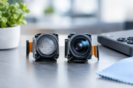
Vibration rarely damages only one component. It can affect the optical stack, sensor package, printed circuit board, FPC cable, connector, solder joints, adhesive bonds, and the housing or bracket that holds the assembly. The first visible symptom may be an intermittent image, but the root cause is often mechanical.
Lens Movement and Focus Shift
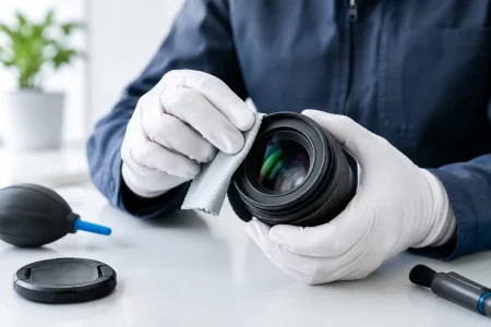
The lens is a common concern, especially with compact modules where small positional changes affect focus and field alignment. Repeated vibration can loosen a threaded lens barrel, fatigue adhesive around a lens holder, or cause slight tilt between the lens and sensor. Even a minor change can reduce sharpness at the image edge, alter calibration, or create inconsistent focus across production units.
For fixed-focus industrial products, lens retention methods should be selected for the expected load. Thread locking, controlled adhesive application, mechanical retention features, and stable lens-holder materials can all help. The trade-off is serviceability. A permanently locked lens may be more stable, but it is harder to rework or refocus during manufacturing.
Solder Joint and PCB Fatigue
A camera module PCB bends under vibration. If the board is thin, unsupported, or connected to a heavy cable, the stress can concentrate around large components, sensor pads, connector pins, or board edges. Over time, solder fatigue may create an intermittent electrical connection that appears only at a certain frequency or temperature.
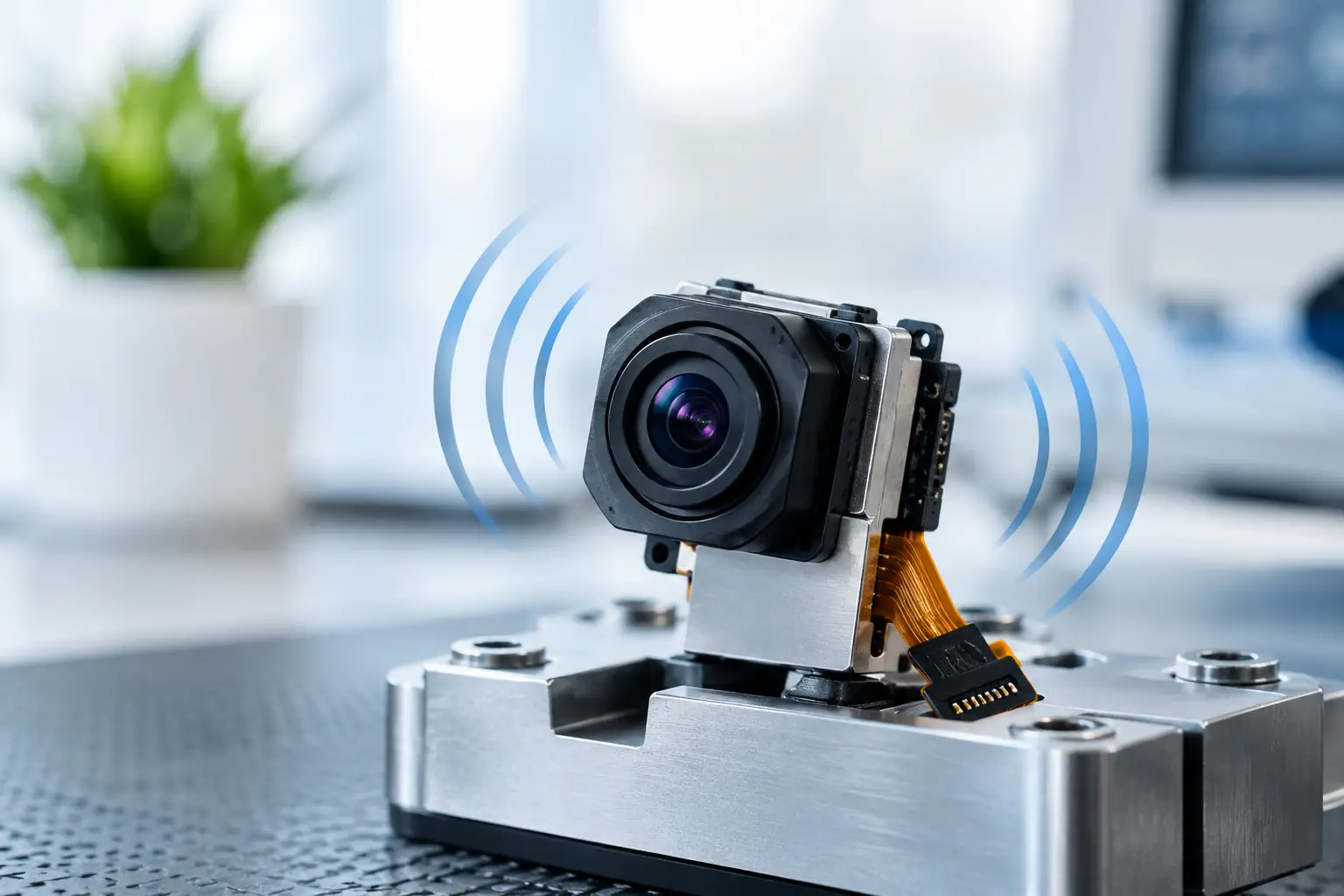
Board thickness, mounting-hole location, component placement, stiffeners, and connector selection all influence reliability. A compact FPC camera module offers excellent packaging flexibility, but the FPC must be routed with proper bend radius, strain relief, and clearance from moving edges. A cable that is allowed to oscillate can transfer substantial force directly into the connector.
Connector and Cable Failures
In many field failures, the camera itself is not the weak point. The failure occurs at the interface between the module and the host system. Board-to-board connectors, FPC connectors, USB connectors, and wire harnesses must remain secure while the equipment moves.
Retention force is only part of the answer. The cable needs a planned strain-relief point near the module, while the connector must not carry the cable’s weight or motion. Connector orientation also matters. A side-loaded connector may see much higher stress than one supported by the enclosure and routed along the direction of movement.
Sensor, Filter, and Adhesive Integrity
Image sensors and optical filters are precisely positioned components. Repeated vibration can stress adhesive interfaces, especially when materials expand differently under heat. In applications with both vibration and wide temperature cycling, an adhesive that survives room-temperature testing may not maintain alignment over the product life.
This is why camera reliability testing should reflect combined conditions where possible. Vibration, thermal cycling, humidity, dust exposure, and electrical operation do not occur separately in real machines.
The Mounting Design Often Determines the Outcome
A well-built module can still perform poorly when mounted to a flexible sheet-metal panel or a long unsupported bracket. The bracket can amplify input vibration at its natural frequency, causing the camera to experience more movement than the machine frame itself.
The goal is not always to make the camera mount as rigid as possible. A very rigid installation can transmit high-frequency energy directly into the module. In some cases, carefully selected isolation materials reduce vibration. However, soft isolation can introduce camera movement, image blur, or calibration drift, particularly in machine vision systems that depend on a fixed camera-to-object relationship.
For inspection, measurement, barcode reading, and robot guidance, mount stiffness and repeatable position usually take priority. For vehicle monitoring or general observation, isolation may be more acceptable. Engineers should evaluate the camera’s required image stability before adding rubber mounts or grommets.
The enclosure also plays a role. A properly designed housing can support the module, protect the lens, provide cable strain relief, and prevent resonance. Potting or conformal coating may improve durability in certain designs, but they add heat-management, repairability, and optical cleanliness considerations. Potting should never be treated as a substitute for a sound mechanical structure.
How to Specify a Vibration-Resistant Camera Module
Start with the use case rather than a generic request for a rugged camera. The most useful input to a camera manufacturer is the location of the module, expected vibration source, mounting method, available space, interface, illumination conditions, and performance target. If available, provide the equipment-level vibration specification or test standard.
A clear engineering brief should also define whether the camera must remain powered and transmitting images during the test. For many embedded vision applications, physical survival is not sufficient. The module must show no frame drops, image corruption, focus shift, connector interruption, or calibration change while operating.
There are four decisions that usually have the greatest impact: selecting a module architecture with appropriate mechanical support; designing a bracket and enclosure that avoid resonance; securing the cable and connector with strain relief; and validating the final installed assembly rather than the camera module in isolation. Each decision is application-specific.
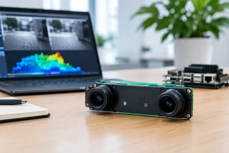
Sensor choice can also affect packaging options. A small MIPI camera module may suit a compact robot or handheld device, while a USB3.0 module may be better for industrial systems that need high bandwidth and simple host integration. The interface does not determine vibration resistance by itself, but it influences cable design, connector selection, board layout, and available mounting space.
Validation Should Measure Image Performance, Not Just Survival
A serious test plan uses pre-test and post-test inspection, then compares optical and electrical performance. Inspect lens alignment, housing condition, solder integrity, connector retention, and cable damage. Capture repeatable image targets before and after exposure to check for focus changes, distortion shifts, dead pixels, noise changes, or image artifacts.
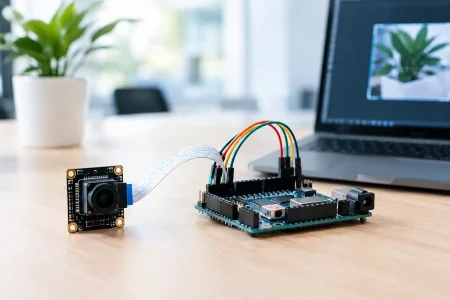
During powered testing, monitor frame continuity and interface stability. An intermittent MIPI, USB, or DVP connection may only appear under a narrow vibration band, making it easy to miss without continuous logging. For systems using auto-focus or optical image stabilization, testing must also confirm that the control behavior remains stable under motion.
Qualification should include the production-intent bracket, fasteners, cable, enclosure, and host board. Testing a loose sample camera on a shaker table is useful for early screening, but it cannot prove that the installed product will endure field conditions.
Custom Engineering Reduces Risk Earlier
When vibration is a known requirement, customization is usually less expensive before tooling and certification than after field failures occur. Useful adaptations can include a reinforced PCB, revised mounting geometry, lens-locking process, custom FPC length and stiffener, alternate connector, protective housing, or an optical design optimized for a fixed working distance.
SincereFirst supports camera module development from sensor and optical selection through mechanical integration and scaled production. For projects in robotics, medical devices, industrial automation, agriculture, and mobile equipment, early review of the vibration environment helps prevent late-stage redesigns and inconsistent field performance.
The best next step is to treat vibration as an imaging requirement, not only a mechanical one. Define what the camera must continue to see, transmit, and measure while the machine is moving, then build the module and installation around that result.