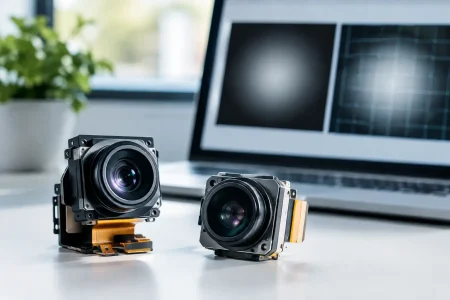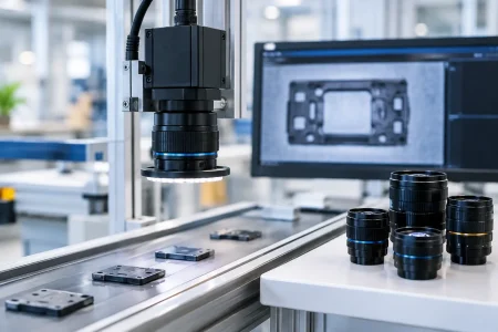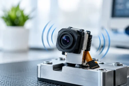

A camera module that produces a sharp laboratory image can still fail in a finished robot, medical instrument, or inspection system. The reason is usually not the sensor alone. Embedded vision integration is the disciplined work of matching optics, sensor performance, interface bandwidth, mechanics, illumination, firmware, and manufacturability to the actual operating environment. When one of these elements is treated as an afterthought, development time expands and field reliability suffers.
For OEMs and system integrators, the objective is not simply to purchase a camera. It is to add an intelligent eye that delivers repeatable image data across every production unit, at the target cost and within the available mechanical envelope.
What Embedded Vision Integration Must Solve
An embedded vision system begins with the scene, not a resolution specification. A warehouse robot may need to read labels while moving under mixed lighting. A medical device may require accurate color, low heat, and a compact distal-end camera. An agricultural system may need to distinguish crop features in bright sun, shadow, dust, and vibration. Each application places different demands on exposure control, dynamic range, lens selection, frame rate, focus distance, and image processing.
This is why a high-resolution module is not automatically the right module. More pixels can improve detail, but they also increase data rate, power use, processing demand, storage requirements, and lens sensitivity. A 2MP module with the right lens and stable exposure may outperform a 13MP module when the real task is barcode capture at speed. The useful question is: what image quality is required for the algorithm or operator to make a reliable decision?
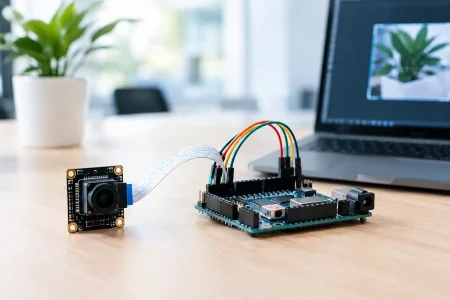
Integration also requires a clear division between what happens on the camera and what happens on the host processor. Some systems need raw image output for custom ISP tuning or AI processing. Others benefit from a UVC USB camera module that simplifies host compatibility and reduces software effort. MIPI CSI-2 is often preferred for compact mobile and embedded platforms, while USB 3.0 can be a practical choice when bandwidth, cable length, and plug-and-play evaluation matter more than minimum size.
Start With the Imaging Requirement, Not the Interface
Teams frequently select an interface before defining the optical and image-performance targets. That shortcut can create a costly redesign. Interface choice should follow the required resolution, frame rate, pixel format, latency, cable length, host platform, and power budget.
A MIPI camera module can provide a compact, high-speed connection for processors with native CSI support. It is well suited to space-constrained smart devices, handheld equipment, and integrated robotics. However, MIPI routing requires careful signal-integrity design, compatible drivers, and disciplined coordination between the camera supplier and the host-board team. It is not always the fastest route to a prototype if the processor platform lacks mature camera support.
USB 2.0 and UVC modules reduce integration complexity for many industrial, security, and computer-connected products. USB 3.0 supports higher data throughput for demanding resolutions and frame rates. The trade-off is physical connector size, cable constraints, and power consumption. DVP interfaces remain relevant for certain legacy or cost-sensitive designs, but they require the host processor to support the parallel timing and data signals.
The correct decision depends on the complete system. A camera module should be evaluated with the intended processor, cable assembly, display or AI pipeline, and enclosure conditions, not as an isolated component.
Define the image before selecting the sensor
Sensor selection should be tied to measurable acceptance criteria. These typically include field of view, working distance, minimum feature size, motion speed, illumination range, acceptable motion blur, color accuracy, low-light noise, and allowable distortion. If the device will use AI inference, the team should test representative images against the actual model. A visually pleasing image is not necessarily the image that produces the best detection accuracy.
Shutter type deserves early attention. Rolling-shutter sensors are compact and widely available, but fast motion or pulsed lighting can introduce geometric distortion. Global-shutter sensors capture the image at one instant and are often the better fit for machine vision, high-speed automation, and moving robotics. They may bring cost, resolution, or low-light trade-offs, so the application should determine the choice.
Optical and Mechanical Decisions Drive Field Performance
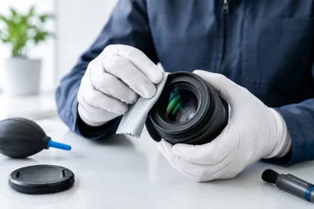
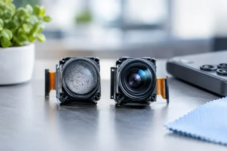
The lens and mechanical stack-up determine whether the sensor can deliver useful information. A sensor with excellent specifications cannot compensate for an unsuitable focal length, insufficient depth of field, lens shading, or focus drift after assembly.
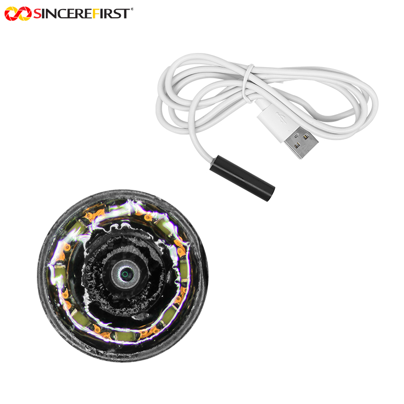
Fixed-focus optics are efficient for high-volume products when the working distance is controlled. They reduce moving parts, calibration complexity, and long-term failure risk. Autofocus can be valuable when users capture subjects across a wide distance range, but it adds control requirements, power consumption, response-time considerations, and additional validation. For endoscope modules and other constrained assemblies, diameter, viewing angle, illumination position, and distal-end heat must be evaluated as a single design problem.
Mechanical tolerances matter just as much in industrial products. The camera must retain alignment through vibration, shock, thermal cycling, and repeated handling. FPC length and bend radius, connector retention, grounding, shielding, and enclosure interfaces all affect installation quality. Small variations in lens position or adhesive cure can shift focus enough to affect a vision algorithm. Production-ready integration therefore needs defined tolerances and verification methods, not only a successful engineering sample.
Illumination is part of the camera system
Many vision projects attempt to solve weak lighting with higher sensor gain. This usually increases noise and produces inconsistent results. Controlled illumination can improve contrast, freeze motion, reveal surface defects, and reduce the burden on downstream software.
The right lighting geometry depends on the feature being inspected. Ring lighting can reduce shadows on certain surfaces, while backlighting is useful for silhouette measurement. Coaxial lighting can help inspect reflective flat objects, and angled lighting may reveal scratches or texture. For medical and endoscopic imaging, color rendering, LED heat, light distribution, and patient-facing safety considerations require equally careful treatment.
Camera exposure and illumination should be designed together. If strobe lighting is used, the sensor must support the required timing behavior. If ambient light changes significantly, automatic exposure behavior must be tested against the real scene rather than assumed from a datasheet.
Build Firmware and Image Tuning Into the Plan
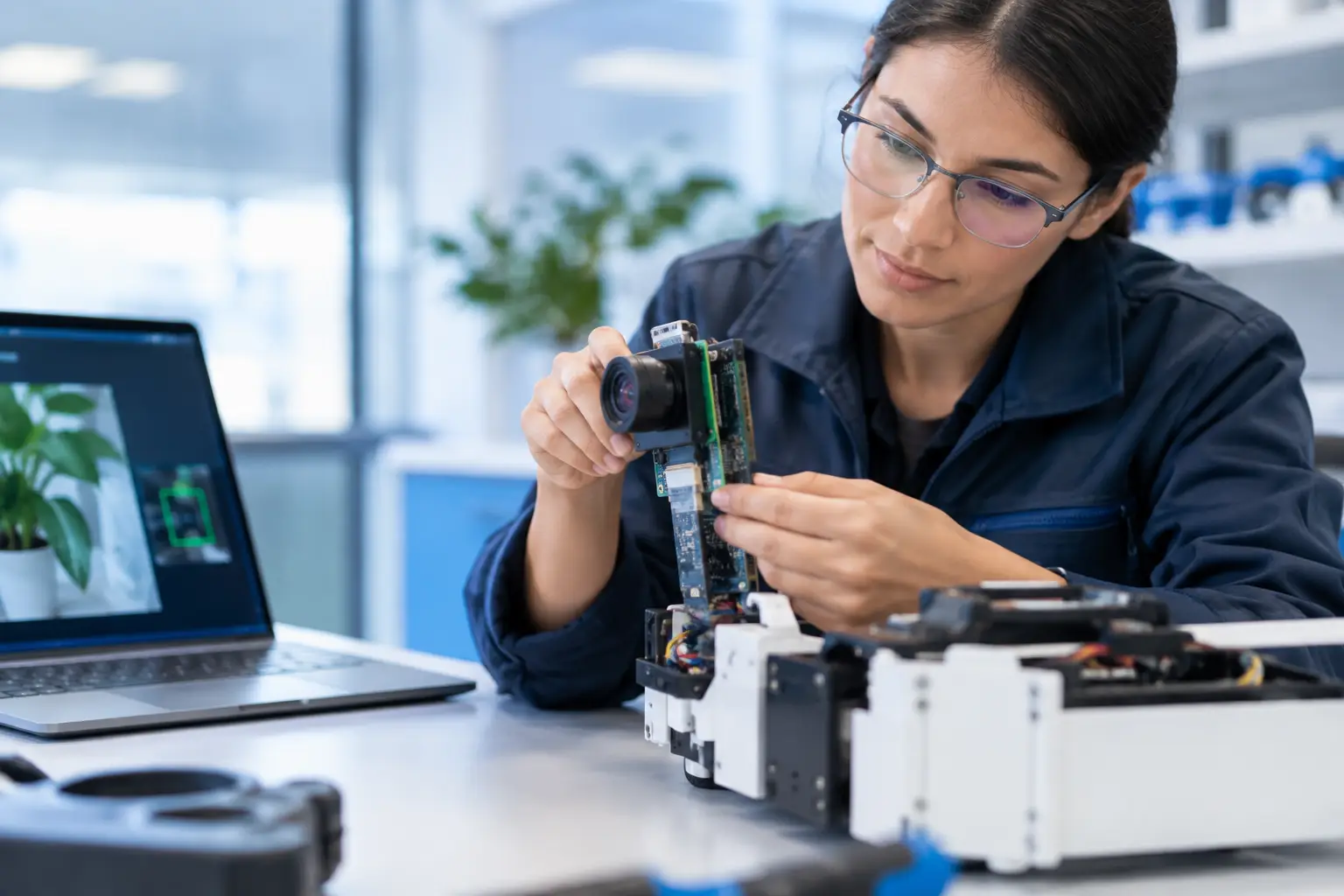
A camera module is not fully integrated when it sends frames to a host. Image signal processor settings can materially change noise, sharpness, white balance, color reproduction, lens shading correction, and exposure stability. Default tuning may be adequate for early evaluation, but commercial products often need application-specific adjustment.
This is especially true when a product uses a custom lens, nonstandard illumination, narrow field of view, or a challenging color target. Over-aggressive noise reduction can remove details needed for inspection. Excessive sharpening can create false edges that confuse machine vision algorithms. Automatic white balance can cause frame-to-frame color shifts that are unacceptable in medical imaging or color-based sorting.
Firmware compatibility should be confirmed early, including operating system support, driver maturity, sensor register access, boot behavior, and recovery after connection faults. A fast sample is valuable, but the production program also needs version control, documented configuration, and a change-management process. Otherwise, a small component revision can introduce an unexpected image change late in qualification.
Plan Embedded Vision Integration for Manufacturing
The transition from prototype to volume production is where many embedded vision programs reveal hidden risk. A module that works on an engineering bench may not deliver the same result after thousands of units, multiple component lots, and final assembly by different operators.
Manufacturing readiness includes incoming inspection standards, sensor and lens traceability, cleanroom assembly where required, focus verification, cosmetic inspection, electrical testing, and image-quality validation. It also includes supply continuity for sensors, lenses, connectors, and FPC materials. Procurement teams should ask how revisions are controlled, how long-term availability is handled, and which tests are performed on every unit versus by sampling.
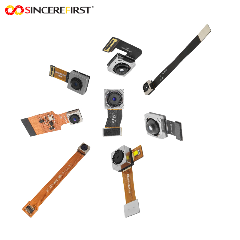
Customization should be evaluated beyond the headline request. Changing an FPC length, connector orientation, lens holder, infrared filter, or housing may affect signal integrity, focus, thermal behavior, assembly yield, or tooling. A capable manufacturer can identify these dependencies early and provide a design path that supports both fast samples and stable scale production.
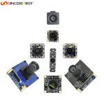
SincereFirst approaches this work as an engineering and manufacturing program, combining camera-module options with customization across sensor selection, interfaces, optics, FPC design, and mechanical integration. That approach is particularly valuable when a standard module can shorten development, but the final device still requires controlled modifications for fit, performance, or volume assembly.
Use a Qualification Plan That Reflects Real Use
A practical qualification plan should test the camera under its intended operating conditions: temperature range, vibration, shock, ambient-light variation, motion, cable stress, and long-duration operation. Test both nominal units and tolerance-boundary units. If a system will operate 24/7, evaluate heat buildup and image drift over time rather than relying only on a short functional check.
Acceptance criteria should be objective. Define minimum resolution at the working distance, allowable dead pixels, color or grayscale targets, signal-to-noise limits, focus tolerance, startup time, frame-drop limits, and interface stability. For AI applications, add task-level metrics such as detection rate, false-positive rate, and confidence stability.
The best embedded vision programs make these decisions early, while sensor, optics, electronics, and manufacturing choices can still be adjusted. That is how a camera module becomes a dependable imaging system – one built to keep seeing clearly long after the prototype has left the lab.