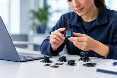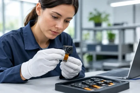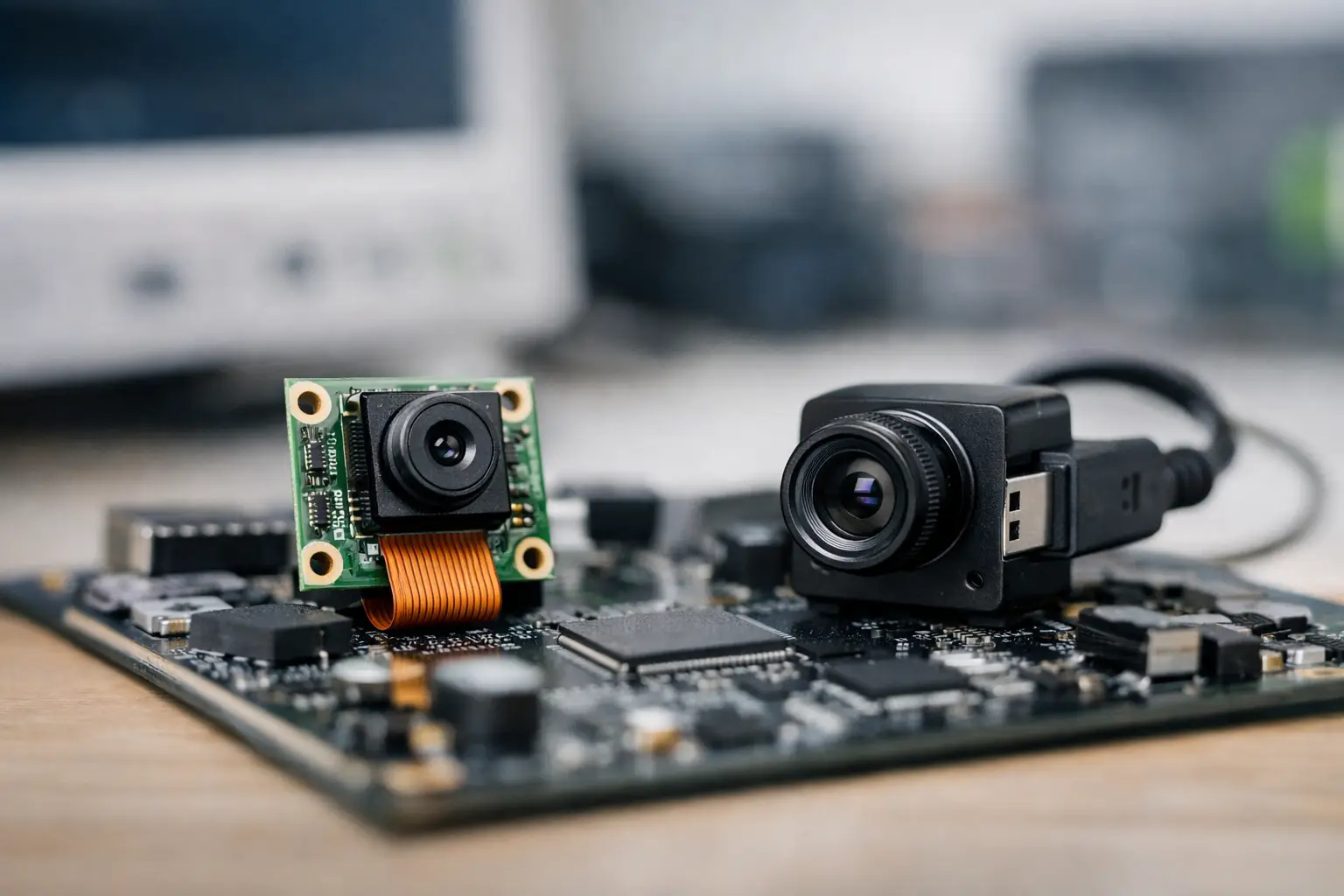
A camera module can meet the resolution target and still delay a product launch because its interface does not fit the processor, enclosure, cable path, or software stack. The MIPI vs USB camera decision is therefore not simply a question of image quality. It is a system architecture decision that affects development time, bill of materials, power design, mechanical layout, and the path from prototype to volume production.
For embedded product teams, MIPI and USB cameras solve different integration problems. MIPI is usually the direct, compact path for tightly integrated smart devices. USB is often the faster path for systems that need standard connectivity, longer cable runs, or broad host compatibility. The right choice depends on where the image data must go and how much control the product requires.
MIPI vs USB Camera: The Core Difference
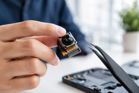
A MIPI camera module typically uses the MIPI CSI-2 interface to connect directly to an application processor, system-on-chip, or embedded board. It transfers image data across dedicated high-speed differential lanes through a short FPC cable or board-level connection. This architecture is common in smartphones, tablets, robotics controllers, compact AI devices, and custom industrial equipment.
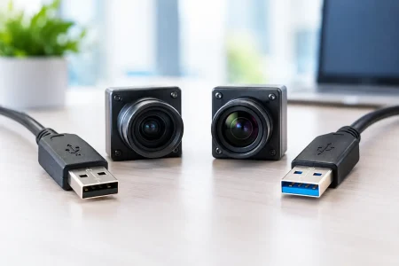
A USB camera module converts its video output into a USB data stream that a host system can recognize through a USB port. Many USB cameras use the UVC protocol, allowing common operating systems to identify them without a custom camera driver. This makes USB especially practical for PCs, single-board computers, kiosks, medical carts, security terminals, and equipment that needs a replaceable external camera.
The sensor itself may be similar in either module. A Sony, OmniVision, or onsemi image sensor does not automatically become better because it is paired with MIPI or USB. The interface determines how the sensor data reaches the host and what engineering work is required around it.
When MIPI Is the Better Choice
MIPI is designed for compact embedded imaging. It offers a direct data path with low protocol overhead, which makes it well suited to high-frame-rate and low-latency applications. In a robot that must react to a moving object, or an AI edge device that processes frames locally, a direct MIPI connection can reduce delays introduced by USB transport and compression.
MIPI CSI-2 also supports high bandwidth through multiple data lanes. The usable throughput depends on the lane count, lane speed, pixel format, resolution, frame rate, and host capability. A two-lane or four-lane MIPI design can carry substantial uncompressed image data, but the processor must have a compatible CSI-2 receiver and sufficient ISP, memory, and processing resources.
The compact mechanical profile is another major advantage. MIPI camera modules commonly use thin FPC cables and small board dimensions, helping device manufacturers fit imaging into handheld terminals, smart locks, wearables, inspection tools, and space-constrained medical equipment. For products where every millimeter matters, USB connectors and cable assemblies may be too large.
MIPI also gives engineering teams more direct control over the imaging pipeline. Depending on the sensor and host platform, developers can tune exposure, gain, white balance, frame timing, region of interest, trigger behavior, and ISP parameters at a deeper level. That flexibility matters when the camera is not just recording video but performing measurement, barcode reading, defect detection, or computer vision inference.
The trade-off is integration complexity. MIPI is not generally plug-and-play. The team must confirm sensor driver support, CSI lane configuration, clocking, power sequencing, I2C control, kernel compatibility, ISP tuning, and FPC pinout. Signal integrity becomes increasingly important as lane speeds rise. A module that works on an evaluation kit may still require careful validation in the final enclosure.
MIPI Fits Products Built Around a Specific SoC
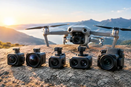
Choose MIPI when the camera is a permanent part of a custom device and the processor platform has native camera support. It is usually the stronger choice for compact robotics platforms, smart appliances, automated guided vehicles, embedded AI terminals, and custom medical devices where latency, size, and imaging control justify the development effort.
For an OEM, the key procurement question is not only whether a MIPI module has the desired sensor. It is whether its output format, lane configuration, lens field of view, operating conditions, and driver support match the target board. Early interface verification prevents expensive redesigns later in the program.
When USB Is the Better Choice
USB cameras prioritize compatibility and deployment speed. A UVC camera can often connect to Windows, Linux, Android, or other supported host environments with minimal driver work. For a team building a proof of concept or bringing a PC-based product to market, that simplicity can shorten the development cycle significantly.
USB is also more practical for applications that need longer cable distance between the camera and processor. A MIPI FPC connection is normally short and internal to the device. USB cable assemblies can support more flexible physical layouts, although reliable distance still depends on USB version, cable quality, shielding, power demand, and electromagnetic conditions.
USB 2.0 camera modules are cost-effective for moderate-resolution video, basic monitoring, document scanning, video conferencing, and many inspection tasks. USB 3.0 camera modules provide much more bandwidth for higher resolutions, higher frame rates, and lower-compression video transport. The practical limit remains a system-level issue: host controller bandwidth, shared USB devices, cable quality, and software processing can all affect real performance.
USB cameras are particularly useful where modular replacement matters. A security terminal, laboratory workstation, telemedicine cart, or industrial PC may benefit from a camera that can be connected, serviced, or upgraded without opening the main electronics assembly. Standardized connectors also simplify integration across product variants.
USB is not automatically lower latency than MIPI in every case, but it usually has more layers between the sensor and application. UVC handling, USB transfers, host scheduling, buffering, and compression can add delay. For video display or general monitoring, this may be insignificant. For precision motion control or real-time machine vision, it needs to be measured under actual operating conditions.
USB Fits Flexible and Host-Agnostic Systems
Choose USB when the host platform varies, when fast software integration is a priority, or when the camera must be located farther from the main processor. It is often the practical fit for PC-connected equipment, embedded Linux systems with limited MIPI support, kiosks, conferencing products, external inspection cameras, and serviceable industrial systems.
A USB module still requires careful selection. Buyers should verify USB 2.0 or USB 3.0 compatibility, UVC support, output resolution and frame rate, compression format, low-light behavior, autofocus or fixed-focus requirements, cable length, connector type, and power consumption. A low-cost module that does not maintain frame stability in the final environment is rarely a low-cost decision.
Compare Bandwidth, Latency, and Image Processing
MIPI normally carries raw or lightly processed image data into the host ISP. This can produce excellent results when the processor has a capable ISP and the team can tune the image pipeline. It also means image quality depends heavily on system software, sensor configuration, lens selection, and calibration.
USB modules may output MJPEG, H.264, YUYV, or other formats depending on the design. Compression can reduce bandwidth requirements but may introduce artifacts or processing delay. Uncompressed formats preserve more direct image information but consume considerably more bandwidth. There is no universal winner: a USB 3.0 camera with a well-matched sensor and ISP can outperform a poorly integrated MIPI design, while a tuned MIPI solution can be the better option for demanding vision tasks.
Power architecture also deserves attention. MIPI modules typically draw power from the embedded board and require correct sequencing across sensor rails. USB can provide power through the cable, simplifying some installations, but the host port must supply enough current and the cable must avoid unacceptable voltage drop. For modules with LEDs, autofocus, or high-power processing, the power budget should be validated early.
Engineering Questions Before Selecting an Interface
Start with the host processor. If it has a validated MIPI CSI-2 input and an available ISP pipeline, MIPI may provide the most integrated result. If the product uses a PC, industrial computer, or host platform that needs a standard camera peripheral, USB may reduce software risk.
Next, define the imaging workload in measurable terms. Required resolution, frames per second, field of view, low-light performance, shutter type, latency tolerance, and image output format should be specified before comparing modules. A 4K camera is not useful if the host cannot receive, process, store, or transmit its data at the intended frame rate.
Mechanical requirements can change the decision quickly. Consider camera board size, lens height, FPC bend radius, connector location, cable length, enclosure shielding, mounting method, and service access. For endoscope, medical, and highly compact optical systems, the physical connection can be as decisive as the data interface.
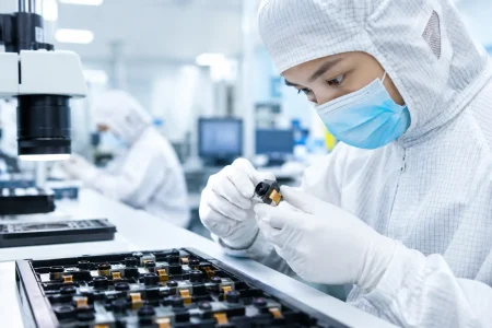
Finally, evaluate the supplier’s ability to support the full program. A camera module may need a custom FPC length, lens angle, infrared filter configuration, connector orientation, housing, firmware setting, or image tuning profile. The best interface is the one that can be validated quickly and manufactured consistently at the required volume.
Select the Interface Around the Product, Not the Spec Sheet
MIPI is usually the stronger architecture for deeply integrated, space-limited devices that require direct sensor control and low-latency processing. USB is often the more efficient choice for standardized, serviceable, host-agnostic products that benefit from rapid deployment. Neither interface should be selected based on resolution alone.
For custom imaging programs, SincereFirst supports camera module evaluation from sensor and optical selection through interface definition and production-ready customization. The productive next step is to test the chosen module with the actual host board, cable path, lighting, and software workload before committing to the final mechanical design.