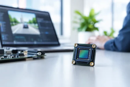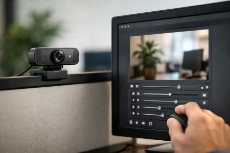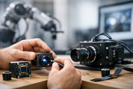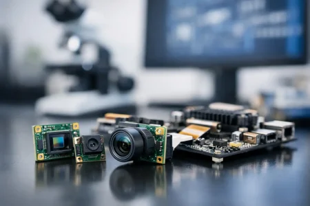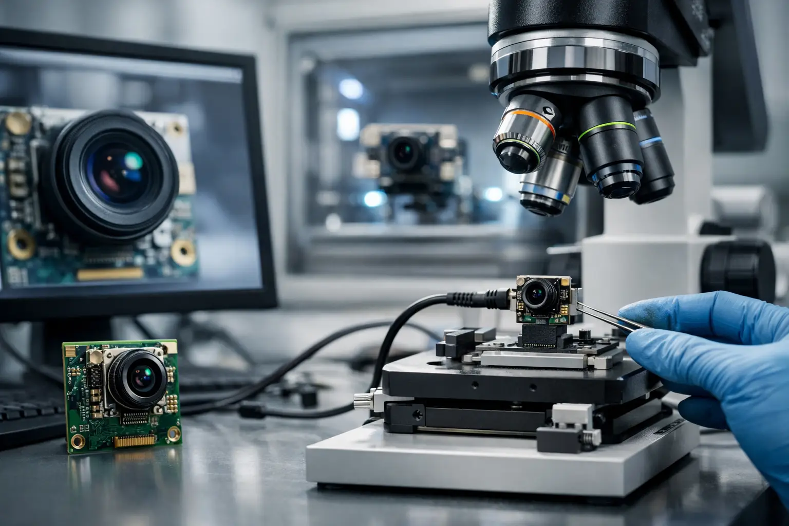
A camera module can pass a bench image check and still fail after six months inside a robot, medical device, or outdoor security unit. Connector fatigue, FPC stress, infrared leakage, focus drift, condensation, and firmware timing faults often appear only after the module is integrated into the real product. That is why knowing how to validate camera module reliability requires more than reviewing a datasheet or approving a few golden samples.
For OEMs and system integrators, reliability validation is a risk-control process. It must confirm that image quality, electrical behavior, mechanical construction, and supply consistency remain within specification through the conditions the finished device will actually face.
Define Reliability Before You Start Testing
Reliability is application-specific. A USB camera used in a climate-controlled kiosk has a different risk profile than a MIPI module mounted in an agricultural machine, an endoscope module subject to repeated handling, or a camera in a vehicle-facing smart-city device. Applying the same test plan to all of them wastes time in some areas and leaves dangerous gaps in others.
Start with a written reliability requirement that connects the module to its operating environment. Define the temperature range, humidity, expected operating hours, shock and vibration exposure, power cycling frequency, storage conditions, cable routing, and required image performance. Also state what constitutes failure. A completely dead module is obvious, but a gradual loss of sharpness, unstable frame rate, intermittent I2C communication, or a growing number of defective pixels can be equally unacceptable.
The acceptance criteria should include measurable limits. For example, specify minimum center and corner sharpness, permitted color variation, maximum dark-current increase, frame-drop allowance, focus shift, and connector insertion-cycle requirements. If the camera uses fixed focus, establish the target object-distance range before evaluating MTF. If it uses autofocus, validate focus time and repeatability as well as final image quality.
How to Validate Camera Module Reliability Across Four Layers
A useful qualification plan evaluates the camera as an optical device, an electronic assembly, a mechanical component, and a manufactured product. These layers interact. A thermal test that appears electrical may reveal lens-barrel movement. A vibration failure may originate in an FPC bend radius rather than the image sensor.
1. Establish a Baseline With Incoming Characterization
Before stressing any samples, record a complete baseline. Test every qualification unit under controlled lighting and electrical conditions. Capture image data for resolution, MTF or SFR, distortion, field of view, shading, white balance, color reproduction, signal-to-noise ratio, dynamic range, defective pixels, and low-light performance where relevant.
Record current consumption, startup behavior, clock and data-line integrity, I2C register communication, output format, frame rate, and temperature at the sensor package. Photograph the module and inspect solder joints, lens seating, adhesive coverage, connector alignment, FPC traces, and protective coatings.
This baseline makes post-stress results meaningful. Without it, a supplier and customer may disagree over whether a corner-sharpness result is a new defect or normal unit-to-unit variation. It also helps engineering teams distinguish an isolated weak sample from a systematic design issue.
2. Test Environmental Endurance
Environmental testing exposes materials and assemblies to conditions that accelerate field aging. The exact profile depends on the application, but temperature cycling, high-temperature operating life, low-temperature operation, damp heat, thermal shock, and storage testing are common starting points.
During temperature cycling, inspect for image artifacts, focus change, cracked solder joints, lens displacement, seal failure, and unstable communication. Thermal shock is more severe because it rapidly changes temperature and can expose mismatched expansion rates among the sensor package, PCB, lens holder, adhesive, and housing.
Humidity testing deserves close attention for modules used outdoors, in medical equipment, or near process machinery. Moisture can cause corrosion, leakage current, fogging, adhesive degradation, and contamination beneath the lens. For an endoscope camera module, the validation plan may also require confirmation that the sealing approach withstands the intended cleaning, handling, and sterilization process. A test is only credible when its conditions match the product’s actual use case.
Run image and electrical checks during selected stress stages when possible, not only at the end. An intermittent failure that occurs at temperature extremes can disappear once the unit returns to room temperature.
3. Verify Mechanical Durability and Integration Risks
Small camera modules are frequently damaged by forces introduced after they leave the factory. A correctly manufactured module can fail when a tight enclosure bends the FPC, a connector is repeatedly serviced, a lens is contacted during assembly, or a moving platform transmits vibration into the board.
Validate vibration and mechanical shock with the module mounted as it will be in the final device. Test both powered and unpowered states when appropriate. Inspect the lens position, focus, solder joints, connectors, and cable terminations afterward, then repeat optical and functional characterization.
For FPC camera modules, pay particular attention to bend radius, routing direction, strain relief, and the position of the stiffener. The FPC should not be treated as an unlimited-flex cable. Define the permitted installation geometry and confirm it with fixture testing. For connector-based modules, test mating force, retention, contact resistance, and insertion cycles using the specified connector pair rather than a substitute.
4. Validate Electrical Stability and System Compatibility
Many apparent camera failures are integration failures. Marginal power sequencing, noisy rails, impedance mismatch, inadequate grounding, or an unstable CSI-2 clock can create artifacts that do not appear on a supplier’s evaluation board.
Test startup and shutdown over the expected voltage range. Cycle power repeatedly and observe sensor detection, initialization time, stream recovery, and register retention where applicable. Review MIPI, USB, DVP, or UVC output under maximum frame rate and target cable length. Check for dropped frames, corrupted packets, intermittent enumeration, and image instability while the host processor is under realistic load.
Electromagnetic compatibility should be considered early, especially for industrial equipment, medical devices, and systems with motors, LEDs, wireless radios, or switching power supplies. The goal is not merely to pass a module-level check. It is to ensure the imaging system continues delivering usable data when the surrounding product is operating.
Use Sample Sizes That Can Reveal Process Risk
Three engineering samples are useful for proving that a design can work. They are rarely enough to prove that production will remain stable. Reliability qualification should include samples from multiple builds, material lots, and production shifts whenever practical.
A sensible plan separates design validation from process validation. Design validation asks whether the selected sensor, lens, PCB, adhesive, connector, and assembly method can meet requirements. Process validation asks whether the supplier can produce that result repeatedly at volume. Both matter to procurement teams because a successful prototype does not protect a product launch from lot-to-lot variation.
Require traceability for the sensor lot, lens lot, PCB revision, firmware version, assembly date, and test records. If a failure occurs, this information speeds root-cause analysis and prevents broad, unnecessary containment actions.
Review Failure Analysis, Not Just Pass Rates
A qualification report that says “passed” provides limited value. Ask for the original conditions, sample count, pass-fail criteria, pre- and post-test data, images, failure descriptions, and corrective actions. When a sample fails, the supplier should isolate the mechanism, verify the correction, and show that the change did not create a new optical or manufacturing issue.
For example, adding adhesive may stop lens movement but introduce outgassing or cure-related stress. A different connector may improve retention but alter stack height or sourcing continuity. Reliable camera development requires this type of cross-functional review between optical, mechanical, electronic, and manufacturing teams.
Make Reliability a Production Control, Not a One-Time Event
Qualification establishes confidence at release. Ongoing quality control maintains it. Production controls should include incoming inspection for critical materials, automated optical checks, functional testing, cosmetic inspection, traceability, and defined sampling plans. For higher-risk applications, monitor process capability for key measurements such as lens alignment, focus position, image uniformity, and electrical current.
A capable camera module partner should also have a disciplined engineering-change process. Any change to the sensor, lens, adhesive, PCB, firmware, connector, or manufacturing location can affect performance. Establish which changes require notification, requalification, customer approval, or updated golden samples before volume shipments continue.
SincereFirst supports this approach by pairing camera module customization with controlled manufacturing and application-focused validation. The right test plan can shorten development cycles, but it should never reduce the evidence required to release a camera into a product that must perform for years.
The practical goal is straightforward: validate the module in the form, environment, and system where it will earn its place. That is where reliability becomes a measurable production requirement rather than a promise on a specification sheet.