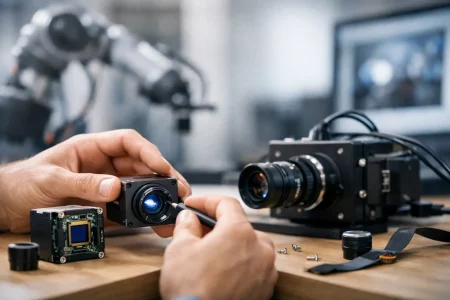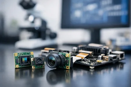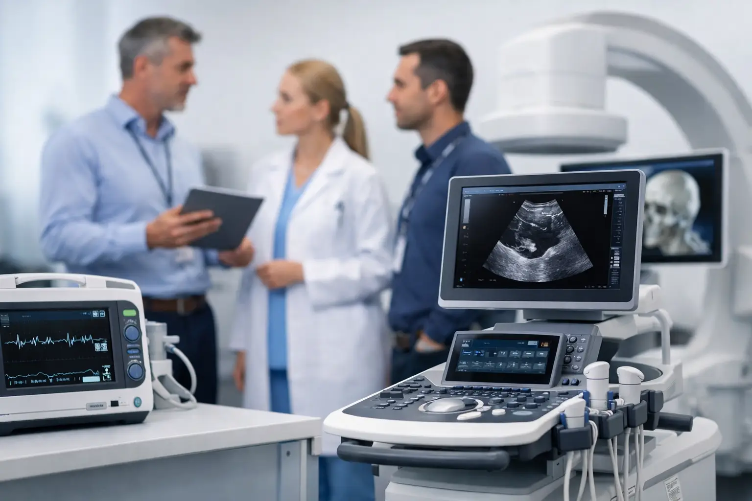
A camera module can meet every electrical target and still create a compliance problem. A medical device imaging compliance guide helps OEM teams connect image quality, patient safety, documentation, manufacturing controls, and regulatory evidence before a design is frozen. For developers of endoscopes, diagnostic instruments, patient monitoring equipment, and image-guided systems, compliance must be designed into the imaging architecture rather than added during validation.
Start With the Device Claim, Not the Camera Spec
The correct compliance path depends on what the finished device is intended to do. A USB camera used to record a procedure, for example, has a different risk profile from an imaging system that supports clinical diagnosis, lesion detection, or surgical navigation. The same sensor can be appropriate in both applications, but the evidence required to support the finished product may be very different.
Define the intended use, users, use environment, patient contact conditions, and image-dependent clinical decisions early. This work establishes whether image performance is merely operational or directly tied to safety and effectiveness. It also prevents a common sourcing mistake: selecting a module based on resolution, frame rate, and price before identifying the quality records and design evidence the device program will need.
For U.S. market access, the device manufacturer should determine the applicable FDA classification and submission route. International programs may also need alignment with ISO 13485 quality management requirements, ISO 14971 risk management, and country-specific registration requirements. A camera module supplier supports this process, but the finished-device manufacturer retains responsibility for the device claim, system-level validation, and regulatory submission.
Medical Device Imaging Compliance Guide: Build a Requirements Chain
A compliant imaging system begins with traceable requirements. Product requirements should flow into camera module specifications, optical requirements, firmware behavior, integration controls, verification protocols, and production acceptance criteria. If the team cannot trace a requirement from user need to objective test evidence, it is difficult to defend during a design review or audit.
Image requirements need more depth than a resolution target. Define minimum usable illumination, field of view, working distance, depth of field, distortion, color accuracy, signal-to-noise ratio, dynamic range, latency, frame loss tolerance, and image artifacts. For a medical endoscope, the relevant test conditions may include tissue-like color targets, LED spectral variation, long cable runs, heat generation, and repeated disinfection exposure at the system level.
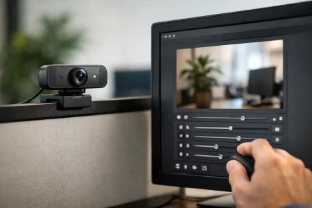
The interface also matters. MIPI CSI-2 can offer low latency and compact integration, while USB UVC can accelerate prototype development and simplify host compatibility. DVP may suit legacy embedded platforms. The best interface depends on bandwidth, processor architecture, electromagnetic compatibility planning, cable length, power budget, and software control. A convenient interface is not automatically the lowest-risk option once the complete medical device is considered.
Use Risk Management to Define Image Failure Modes
Image quality is a patient-safety issue when the user relies on the image to make a clinical decision or guide an action. The risk file should identify foreseeable image failures, their causes, their clinical consequences, and the controls that reduce unacceptable risk.
Relevant failure modes often include frozen video, corrupted frames, incorrect orientation, inadequate illumination, dead pixels, focus shift, excessive latency, false color reproduction, image noise, and intermittent connector contact. In a reusable endoscopic platform, contamination or optical degradation may become a system-level concern. In a portable device, low-battery behavior or temperature-related sensor noise can affect image usability.
Each control should be verifiable. A requirement such as “high image quality” cannot be tested consistently. A better requirement specifies measurable conditions: for example, no frame loss during a defined operating period, maximum latency at a stated resolution and frame rate, or a minimum contrast threshold under defined illumination. Design teams should also decide how the device communicates a degraded image state. In some applications, an alert, image-quality indicator, or controlled shutdown may be more appropriate than allowing the operator to continue with unreliable visual information.
Verify the Module and Validate the Complete System
Verification confirms that the design outputs meet stated requirements. Validation confirms that the finished device meets user needs in its intended environment. These activities overlap, but they are not interchangeable.
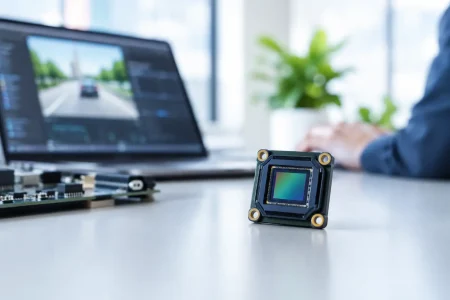
At the module level, test plans should cover optical, electrical, mechanical, and interface performance. Typical evidence includes sensor identification, lens parameters, image tuning version, resolution, frame rate, power consumption, operating temperature, connector definition, mechanical dimensions, and inspection criteria. For modules with onboard image processing, firmware revision control and change history are equally significant.
At the system level, the camera must be tested with the production host processor, display, illumination source, cable assembly, enclosure, power architecture, and user workflow. A module that produces clean images on a bench can behave differently after integration because of electromagnetic interference, thermal buildup, power ripple, display color calibration, compression, or software timing.
Electrical safety and electromagnetic compatibility are also system concerns. Depending on the device type, IEC 60601-series standards may apply. If the device includes software that processes, stores, transmits, or displays medical images, the development process may require software lifecycle evidence aligned with IEC 62304. Usability engineering under IEC 62366 can be relevant when operators must interpret visual alerts, select camera modes, or respond to image loss. Cybersecurity requirements should be considered when imaging data is networked, remotely accessed, or stored.
Qualify the Camera Module Supplier Beyond Samples
A good prototype sample proves that an image can be captured. It does not prove that thousands of units will be electrically consistent, optically stable, traceable, and available through the device lifecycle. Supplier qualification should examine engineering capability and manufacturing discipline together.
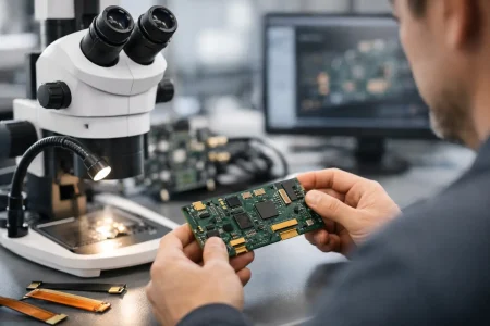
For an imaging module supplier, request clear documentation on component traceability, incoming inspection, cleanroom controls where applicable, production testing, calibration methods, lot identification, and nonconformance handling. Ask how sensor or lens substitutions are controlled, what notification process applies to material changes, and whether the supplier can maintain the approved bill of materials for the required product life.
The supplier package should be proportional to the device risk and program stage. For higher-risk or image-critical applications, OEM teams commonly need the following evidence:
- Approved mechanical drawings, interface definitions, and revision-controlled specifications
- Bill of materials information and component lifecycle status
- Optical and electrical test methods with defined acceptance limits
- Lot traceability and records for production inspection or final test
- Change-control procedures covering sensors, lenses, firmware, connectors, and assembly processes
- Material declarations and applicable environmental compliance documentation
SincereFirst supports this type of supplier evaluation by combining standard camera module platforms with customized optical, interface, and mechanical development for OEM programs. The practical value is not only a fast sample turnaround. It is the ability to carry an approved design into controlled volume production without losing configuration discipline.
Control Changes After Design Freeze
Imaging designs are especially exposed to supply-chain changes. Sensor manufacturers discontinue parts, lenses are updated, image signal processor firmware changes, and connector availability can shift. Even a substitute that appears equivalent may change color response, low-light behavior, focus tolerance, power consumption, or electromagnetic emissions.
Establish a formal change-control agreement before production. It should define which changes require advance notification, what supporting test data is needed, who approves the change, and when the OEM must repeat verification or validation. For medical programs, “form-fit-function equivalent” should not be accepted without evidence tied to the approved system requirements.
A dual-source strategy can reduce continuity risk, but it can also increase verification effort. If two camera modules produce meaningfully different images, the OEM may need separate tuning, test limits, and labeling controls. The best approach depends on annual volume, product lifecycle, clinical criticality, and the cost of maintaining multiple qualified configurations.
Keep the Technical File Ready for Review
Compliance evidence is most useful when it is organized while development is underway. Waiting until submission, transfer to manufacturing, or customer audit preparation often exposes missing test conditions, unclear revisions, and undocumented engineering decisions.
Maintain a controlled file that connects intended use, design inputs, risk analysis, supplier records, test protocols, test results, software versions, production controls, and design changes. The format can vary by quality system, but the objective is constant: an independent reviewer should be able to understand what was built, why each requirement exists, how it was tested, and whether the released product matches the approved design.
For OEM teams, the strongest imaging compliance strategy is practical and disciplined. Choose a camera architecture that fits the clinical use case, measure the failures that matter, qualify the supplier for repeatable production, and treat every controlled change as a potential system impact. That approach protects the development schedule while building the evidence needed to bring reliable medical imaging devices to market.