A camera module can pass a basic power-on test and still fail where the end product matters most: under low light, at the edge of the field of view, after thermal cycling, or halfway through a production run. Effective optical module quality control is therefore not a final inspection activity. It is a controlled manufacturing system that protects image performance from component receipt through shipment.
For OEMs, device makers, and system integrators, this distinction has commercial consequences. A weak module can create field returns, recalibration work, delayed certification, and inconsistent user experience long after a product leaves the factory. A qualified module supplier must demonstrate more than a clear image on a sample unit. It must show that the same optical, electrical, and mechanical result can be repeated across lots and at volume.
What Optical Module Quality Control Must Protect
An optical module is a tightly coupled assembly. The image sensor, lens, FPC or PCB, connector, adhesive, infrared filter, housing, illumination components, and firmware settings all affect the final output. A small deviation in one area can alter sharpness, color response, focus position, noise, or interface stability.
That is why quality control must cover four connected outcomes: component conformity, assembly precision, image quality, and long-term reliability. Testing only one of these areas leaves avoidable risk. A sensor may meet its electrical specification, for example, while lens alignment or adhesive cure variation creates unacceptable corner blur after assembly.
Acceptance criteria also need to match the application. A USB camera module for document scanning, a MIPI module for a compact robotic device, and a medical endoscope module do not have identical tolerance priorities. A medical or industrial inspection system may place greater weight on uniform illumination, focus stability, color repeatability, and traceability. A consumer smart device may prioritize thin mechanical dimensions, low power consumption, and high production yield. The correct control plan depends on the operating environment and the function the image must perform.
Build Quality In Before the Production Line
Reliable output begins with design for manufacturability. Before mass production, engineering teams should convert application requirements into measurable module specifications. “Clear image” is not a usable production requirement. Resolution, field of view, focus range, minimum illumination, frame rate, distortion allowance, signal-to-noise ratio, color targets, interface behavior, and operating temperature range are measurable.
The same discipline applies to mechanical requirements. Module height, active optical axis location, connector orientation, FPC bend area, mounting datum, and lens barrel clearance should be defined early. An optically capable design may still be difficult to build consistently if it requires unrealistic alignment tolerance or exposes a delicate FPC to repeated assembly stress.
Golden samples are valuable at this stage, but they should not become the only reference. A golden sample proves what is possible under controlled conditions. A production specification defines what is acceptable every day, across operators, machines, material lots, and shifts. The supplier and customer should agree on this specification before production release, especially when a custom lens, sensor, housing, or firmware configuration is involved.
Incoming Material Control Sets the Baseline
No inspection station can fully recover quality lost through unstable incoming materials. Sensors, lenses, filters, connectors, FPCs, passive components, adhesives, and housings require supplier qualification and incoming checks based on their risk to the module.
For image sensors, verification may include packaging condition, date code, part marking, electrical checks, and defect screening. Lens inspection should address cosmetic defects, focal characteristics, thread condition, coating condition, and contamination. FPC and connector checks should confirm dimensions, pad integrity, pin alignment, and mating reliability. For adhesives, lot traceability, storage condition, working time, and cure profile matter because bonding variation can affect both lens position and long-term durability.
Sampling plans are practical for stable, low-risk materials, while critical components may justify tighter inspection or full-lot verification. The right choice depends on supplier history, component complexity, the cost of failure, and whether a defect can be detected later in the process.
Control the Assembly Steps That Change the Image
Clean manufacturing conditions are not a marketing detail for optical modules. Dust, fibers, fingerprints, and adhesive residue can become visible image defects. Cleanroom discipline, controlled handling, appropriate protective packaging, and inspection under suitable illumination reduce contamination before it reaches the image sensor or lens surface.
Lens assembly requires special attention. The lens must be seated, aligned, and focused to the specified working distance. In fixed-focus products, active alignment or calibrated mechanical focus adjustment may be necessary to achieve repeatable modulation transfer performance across the field. A lens that appears sharp at the center can still fail because the corners are soft, the focus plane is tilted, or the effective field of view is out of tolerance.
Adhesive dispensing and curing are equally consequential. Too little adhesive can reduce mechanical retention; too much can contaminate the lens, sensor area, or moving interfaces. Cure conditions must be controlled because shrinkage, incomplete cure, or thermal stress can shift focus after the module has passed initial testing.
Electrical assembly must be monitored alongside optics. Poor solder joints, damaged traces, connector misalignment, or electrostatic discharge damage may cause intermittent failures that are not obvious in a short image test. Process controls should include ESD protection, controlled solder profiles where applicable, visual workmanship criteria, and electrical continuity checks.
Use Image Testing That Reflects Real Performance
Image testing should measure performance rather than simply confirm that the camera streams video. Depending on the module and application, final test stations may evaluate resolution, center and corner sharpness, color reproduction, white balance, exposure response, fixed-pattern noise, dead or bright pixels, shading, distortion, frame rate, and interface communication.
Test conditions must be repeatable. Light source color temperature, target distance, test chart quality, environmental lighting, camera settings, and software version can all change the result. Without controlled test conditions, a factory may generate data that looks precise but cannot be compared meaningfully from one shift or lot to another.
Automated image analysis is particularly useful in volume programs because it applies the same thresholds to every unit and captures data without depending solely on subjective visual judgment. Human visual inspection still has a place for cosmetic defects, unusual artifacts, and assembly workmanship, but it works best as part of a defined inspection process rather than as the primary image-quality decision.
Test the Interface, Not Just the Sensor Output
The module must also perform within its intended system architecture. MIPI CSI-2 modules require verification of signal integrity and compatible configuration with the target processor. USB and UVC camera modules need stable enumeration, streaming, frame-rate behavior, and power performance. DVP interfaces require correct timing and output format validation.
This is where supplier engineering support adds value. A module may meet its standalone test requirements but show exposure, clocking, power, or driver issues after integration. Early testing with the customer’s host platform, cable constraints, and operating software reduces the chance that a system-level issue is misdiagnosed as a camera defect.
Reliability Testing Finds Failures Final Inspection Cannot
A clean image at room temperature is only one moment in a module’s life. Reliability evaluation exposes weaknesses related to materials, assembly, and operating conditions. Typical programs may include high- and low-temperature storage, thermal cycling, high-temperature operating tests, humidity exposure, vibration, mechanical shock, connector mating cycles, and extended streaming operation.
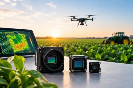
Not every project needs the same test matrix. A short-lifecycle indoor device and an agricultural camera operating through heat, vibration, dust, and changing light require different qualification priorities. The key is to build the test plan around the actual use case, not a generic checklist.
Reliability testing should also feed back into process improvement. If thermal cycling reveals focus shift, the answer may involve adhesive selection, cure parameters, lens retention design, or material expansion compatibility. If vibration causes intermittent output, the investigation may focus on FPC routing, connector retention, solder joints, or housing support. Quality control is most effective when failure data changes the process rather than merely rejecting affected units.
Traceability Turns Quality Data Into Action
Traceability connects a finished module to its sensor lot, lens lot, key material batches, assembly date, test result, and production station. When a customer reports an issue, this information allows the manufacturer to isolate the scope quickly instead of treating every shipment as suspect.
For scaled production, serial-level or lot-level records can support trend analysis. A gradual rise in corner sharpness variation, connector failures, or image noise may reveal a material or process shift before it becomes a field problem. Statistical process control is valuable here because it highlights movement within the acceptable range, where prevention is less costly than containment.
SincereFirst applies this engineering-led approach across standard and customized camera module programs, combining controlled manufacturing with image, interface, and application-focused validation. For buyers, the most useful supplier conversation is not “Do you inspect quality?” It is “Which characteristics do you control, how are they measured, and what data can you provide?”
A dependable imaging product starts with a module designed to be measured, built, and repeated. When quality gates reflect the real application, production scale becomes a source of confidence rather than a new source of variation.