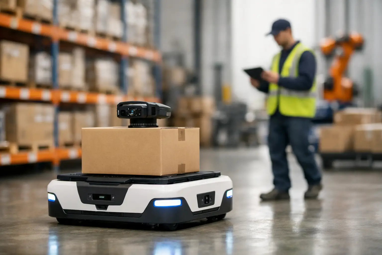
A warehouse robot vision deployment example becomes useful when it starts with a real operating constraint: a mobile robot must collect totes from mixed storage lanes, confirm the pickup location, and deliver each tote to a packing station without relying on perfectly positioned labels or uniform lighting. The robot’s camera system is not a peripheral feature. It is the sensing layer that determines whether the machine can identify a tote, estimate its position, avoid an obstruction, and recover when the warehouse changes.
For OEMs and system integrators, the deployment question is rarely just which camera has the highest resolution. The practical question is which imaging architecture will produce repeatable decisions across shift changes, dust, vibration, reflective packaging, aisle shadows, and the production volumes required for a commercial robot program.
Warehouse Robot Vision Deployment Example: Tote Transport
Consider an autonomous mobile robot designed for tote transport in a distribution center. It travels between shelving, induction areas, and pack stations. At each pickup point, it must verify the tote ID, detect the tote’s front edge, estimate its distance and orientation, then position its lifting mechanism within a narrow tolerance.
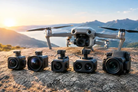
A common vision configuration uses two camera paths rather than asking one module to do every job. A forward-facing wide-angle camera supports navigation, obstacle recognition, and aisle awareness. A second, more tightly framed camera is mounted near the lifting assembly to inspect the tote face and guide final alignment. This division improves image quality at each working distance and reduces the processing burden created by a single ultra-wide camera.
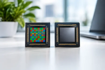
The navigation camera may use a MIPI CSI-2 module with a 2-megapixel to 5-megapixel sensor, depending on the embedded compute platform and required detection range. A 1080p output at 30 frames per second is often sufficient for indoor mobile navigation when the robot speed is controlled. The docking camera may use a global-shutter sensor if tote movement, forklift traffic, or vibration creates motion blur under short exposure conditions.
The key is matching the sensor, lens, interface, and illumination to a defined image task. A high-resolution rolling-shutter module can be cost-effective for barcode reading on a stationary tote. It may be the wrong choice for close-range alignment when the robot is moving over uneven concrete.
The Image Tasks Define the Camera Specification
In this example, the system has four distinct visual tasks: obstacle detection, tote localization, barcode or label verification, and pickup confirmation. Each has different requirements.
Obstacle detection needs a broad field of view and adequate dynamic range. The robot must see a dark pallet jack entering from a bright loading-door area, while still retaining usable detail in shelf shadows. A lens in the 100 to 120 degree horizontal field-of-view range may suit this role, but lens distortion must be calibrated because localization accuracy deteriorates when distorted edge pixels are treated as linear measurements.
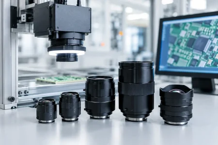
Tote localization requires stable geometry. If the camera is mounted 400 mm from the target and the robot must place a lift plate within a few millimeters, lens selection and mechanical rigidity matter as much as sensor resolution. A moderate field of view can preserve more pixels on the tote face, improving edge detection and pose estimation.
Label verification depends on code size, contrast, print quality, and working distance. A warehouse with clean, standardized labels may read codes with a compact 1080p module. If labels are small, damaged, or placed inconsistently, the system may need a higher-resolution sensor, controlled lighting, or a separate fixed scanner. Vision should not be forced to solve a labeling process problem that can be corrected upstream.
Pickup confirmation is often the most overlooked task. After the lift engages, the robot needs to know whether it has one tote, no tote, or an incorrectly seated tote. A downward-facing camera can verify tote presence and detect unusual gaps. This simple confirmation step prevents a failed pickup from becoming a downstream inventory exception.
Why Lighting Often Determines Field Performance
Warehouse lighting is rarely designed for machine vision. LEDs can create flicker, skylights introduce strong daylight variation, and glossy shrink wrap produces specular reflections that confuse conventional detection models. A camera module with strong low-light sensitivity helps, but controlled illumination is usually the faster path to consistent inspection.
For the docking camera, an integrated LED ring or angled side light can make tote edges and labels more repeatable. The illumination should be selected with the camera exposure strategy, not added after image-quality problems appear. A short, synchronized LED pulse can reduce blur and suppress ambient variation, provided the sensor and driver timing support it.
There is a trade-off. Added lighting increases power demand, thermal load, enclosure complexity, and bill of materials cost. For a robot fleet, those factors multiply quickly. The best design uses controlled light only where it materially improves a critical decision, such as final pickup alignment or code verification.
Global Shutter, Rolling Shutter, and Frame Rate
Global shutter sensors expose all pixels at the same time. They are well suited to moving robots, quick turns, vibrating camera mounts, and targets that pass through the frame rapidly. They can reduce skew in tote edges and improve the reliability of classical measurement algorithms.
Rolling shutter sensors are often more available at higher resolutions and attractive price points. They can perform well for navigation or stationary inspection when exposure times are short and robot motion is limited. The decision depends on actual motion at the image plane, not on a blanket rule that every warehouse robot requires global shutter.
Frame rate should also follow the control loop. A robot moving slowly into a pickup position may need clean 30 fps images with predictable latency more than 60 fps video. Conversely, a fast conveyor-transfer robot may need higher frame rate and a global shutter to maintain adequate image sharpness. Engineers should measure end-to-end latency from exposure through inference and motion command, not merely quote the camera’s maximum frame rate.
Integration Details That Affect Production Readiness
A successful prototype can fail during pilot deployment if the camera module, cable, connector, and enclosure were not designed as one assembly. Mobile robots place unique demands on imaging hardware. Continuous vibration can loosen connectors. Long cable runs can affect signal integrity. Dust accumulation can reduce contrast. Heat from processors and motor drivers can raise sensor noise or shift focus in marginal optical designs.
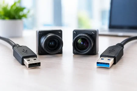
For embedded robot platforms, MIPI camera modules provide low-latency integration with many SoCs, but cable length and board layout need careful control. USB 3.0 camera modules simplify connection to industrial PCs and can support higher data throughput over practical cable lengths. UVC compatibility can accelerate early software development, although commercial deployment may still require control over exposure, gain, synchronization, and firmware behavior beyond basic UVC defaults.
Mechanical integration deserves equal attention. The lens should be secured against focus drift, the optical window should be positioned to minimize glare, and the module should be protected without blocking airflow or creating internal reflections. If the robot operates in refrigerated zones, condensation and temperature transitions must be evaluated early. An IP-rated enclosure alone does not guarantee a clear optical path.
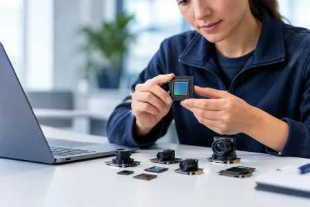
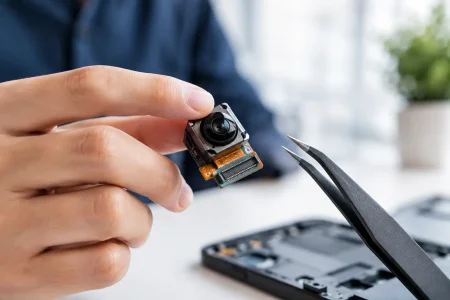
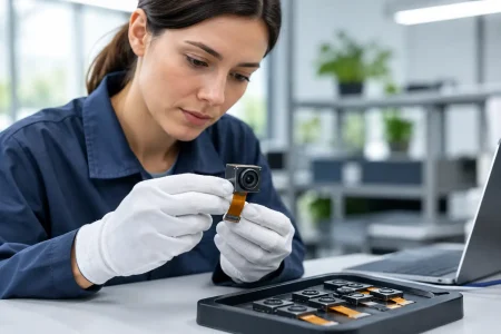
This is where a custom module approach can be more efficient than adapting a catalog camera indefinitely. Sensor selection, lens field of view, focus position, FPC length, connector orientation, LED placement, and housing dimensions can be defined around the robot’s actual geometry. SincereFirst supports this type of camera-module customization from sample development through scaled manufacturing, helping product teams avoid a late redesign caused by an imaging component that does not fit the production enclosure.
Validation Must Include Bad Warehouse Conditions
Vision validation should not be limited to a clean lab with one tote type. The deployment plan should collect images across every expected operating condition: morning and evening lighting, empty and full totes, faded labels, shiny packaging, dirty floors, partially blocked aisles, different forklift speeds, and camera-window contamination.
Build acceptance criteria around decisions rather than attractive images. For example, the docking camera may need to localize the tote within a specified positional tolerance in 99.5% of approved pickup cycles. The label reader may need a defined first-pass read rate, followed by a controlled retry procedure. Obstacle detection should be tested for false negatives as well as nuisance stops, because excessive false positives can reduce fleet throughput.
A staged rollout is usually the soundest approach. Begin with a controlled lane, log images and robot decisions, then expand to more variable zones. Store difficult image cases with timestamps and robot pose data so the team can distinguish optical limitations from model errors, motion-control issues, or process exceptions. This evidence is also valuable when qualifying a camera supplier and freezing the production specification.
The Practical Deployment Lesson
The strongest warehouse robot vision systems are designed around the decisions a robot must make at each moment, not around a camera data sheet alone. A wide-angle navigation view, a precision docking view, targeted lighting, stable mechanics, and realistic validation create a system that can operate beyond a demonstration route.
For robot manufacturers, the productive next step is to turn each visual task into measurable requirements for distance, field of view, motion, latency, illumination, interface, and lifetime. That discipline gives engineering teams a clearer path from a promising prototype to an imaging platform that can be manufactured consistently across an entire fleet.