A camera module can meet every sensor, lens, and resolution target on paper yet still fail at integration because the interconnect was selected too late. Board camera connector types determine how image data, power, control signals, and sometimes illumination reach the host system. They also affect assembly yield, enclosure layout, vibration resistance, serviceability, and the practical path from prototype to volume production.
For OEMs building robotics, medical devices, industrial equipment, security terminals, or compact smart products, the connector is not a minor mechanical detail. It is part of the imaging architecture. The correct choice depends on the camera interface, available board space, cable length, required bandwidth, environmental conditions, and how the finished product will be manufactured.
Board Camera Connector Types: Start With the Interface
A connector and a camera interface are related, but they are not the same thing. MIPI CSI-2, USB, DVP, LVDS, and Ethernet describe how data is transferred. FPC, board-to-board, wire-to-board, and USB receptacles describe the physical connection that carries those signals.
This distinction prevents a common sourcing error: specifying a “MIPI connector” without defining lane count, pitch, pin assignment, cable orientation, shielding needs, and host-side connector requirements. Two MIPI camera modules may use different FPC pin counts and still be electrically compatible only after a custom flex cable or adapter board is designed.
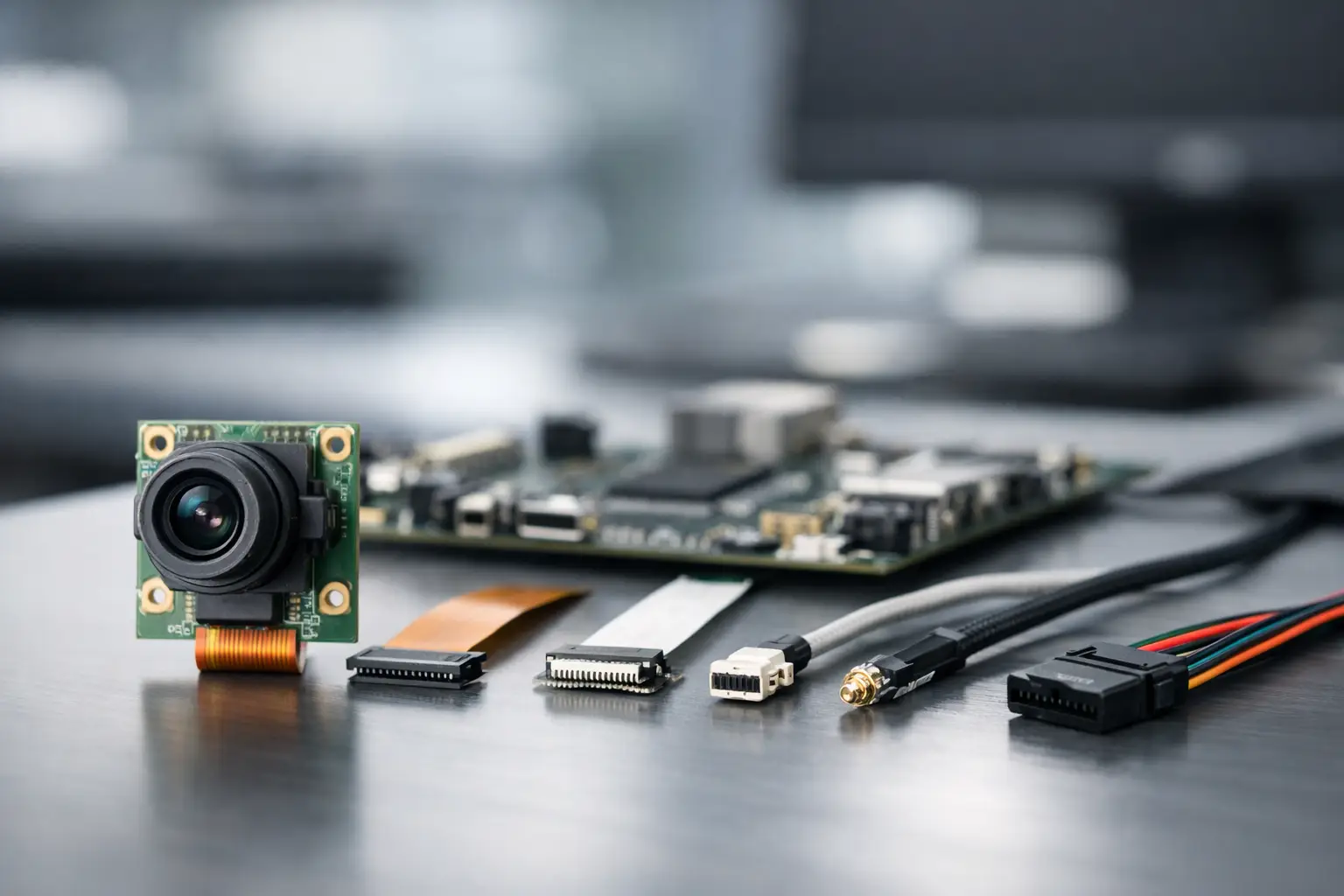
In compact embedded products, FPC/FFC connectors and board-to-board connectors are the most common options. USB camera modules typically use USB connectors or internal cable assemblies, while DVP designs may use FPC connectors, headers, or board-to-board connections depending on the available pin count and mechanical layout.
FPC and FFC Connectors for Compact Camera Modules
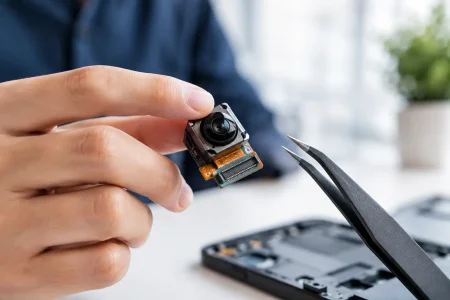
Flexible printed circuit connectors, often called FPC or FFC connectors, are widely used with MIPI camera modules, DVP camera modules, and ultra-compact imaging assemblies. The camera PCB connects to the main board through a flexible cable, allowing designers to position the sensor and lens independently from the processor board.
This format is particularly valuable when the camera must fit into a thin enclosure, a narrow bezel, a handheld device, or a probe. It is also common in endoscope camera assemblies, where the imaging head and control electronics must be physically separated.
The main advantages are low profile, light weight, and routing flexibility. An FPC cable can bend around internal structures that would make a rigid board connection impossible. It also gives enclosure teams more freedom to place the lens at the required optical location rather than directly above the processor.
The trade-off is that FPC connections need disciplined mechanical design. Pitch, contact orientation, cable thickness, stiffener location, bend radius, and locking style must match. For high-speed MIPI CSI-2 signals, cable length and impedance control matter as much as the connector family. A long or poorly controlled flex can create signal integrity problems that do not appear during short bench tests.
Zero insertion force, or ZIF, FPC connectors are common because a locking actuator holds the flex securely after insertion. Front-flip and back-flip versions change the cable entry direction and can determine whether a module fits within the final housing. For designs exposed to frequent handling or vibration, the latch design and strain relief deserve early review.
Board-to-Board Connectors for Rigid, High-Density Assembly
Board-to-board connectors, also called mezzanine connectors, join the camera module directly to a host PCB or an intermediate board. They are a strong choice when the module can be mounted close to the processor board and the product benefits from a rigid, repeatable stack-up.
A board-to-board connection can reduce cable handling, simplify assembly, and provide a compact production-ready architecture. It is often preferred in industrial cameras, fixed inspection equipment, access-control terminals, and other systems where the optical position is stable and the board layout can support direct mounting.
High-density mezzanine connectors can carry MIPI data lanes, I2C control, clock signals, power rails, reset lines, and synchronization signals in one interface. The connector must be selected with enough pin capacity and appropriate ground pin placement to protect high-speed signals. Mechanical stack height is equally critical. A connector that is electrically correct but raises the lens by even a few millimeters may conflict with the housing, light pipe, gasket, or optical alignment requirement.
Compared with FPC, board-to-board designs generally offer less placement freedom. They also demand tighter PCB tolerances and careful consideration of mating cycles. If the module will be disconnected only during factory assembly, a standard low-cycle connector may be suitable. If technicians will replace modules in the field, the connector needs a service-life rating that matches the maintenance plan.
Wire-to-Board Connectors for Remote or Rugged Functions
Wire-to-board connectors are useful when the camera is separated from the host by a cable assembly that requires discrete conductors, stronger retention, or a custom harness. They are often selected for power, trigger, LED illumination, or lower-speed control connections rather than unshielded high-speed image data.
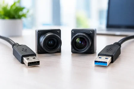
For a USB camera module, a cable harness with a USB connector or a custom wire-to-board termination may be practical when the camera is mounted remotely inside a machine. The choice depends on cable length, electromagnetic interference, expected vibration, and whether the product needs external user access to the USB port.
Locking wire-to-board systems can provide better retention than a small unlatched flex connector in high-vibration equipment. However, they consume more space and can add manual assembly steps. They are not automatically the best answer for MIPI CSI-2 or other sensitive high-speed signals. If a remote camera requires higher bandwidth over a longer distance, consider whether serializer/deserializer architecture, USB 3.0, or another transport method is more appropriate than extending a native board-level interface.
USB Connectors and Internal USB Cable Assemblies
USB camera modules simplify host integration because USB is broadly supported by processors, PCs, and operating systems. USB 2.0 modules are often sufficient for moderate-resolution video, while USB 3.0 supports substantially higher data throughput for high-resolution or higher-frame-rate applications.
The physical connection may be a USB Type-C, Micro-B, Type-A, or internal USB cable assembly, depending on the application. For embedded production, an internal locking cable or board-mounted connector is frequently more reliable than relying on a consumer-facing external port.
Connector selection should account for power delivery, connector insertion life, shielding continuity, and cable quality. USB is more forgiving than a direct MIPI connection in many system layouts, but it is not immune to voltage drop, radiated noise, poor grounding, or intermittent contacts. In factory automation and medical equipment, cable retention and cleanability can be more decisive than convenience.
DVP Camera Connections: More Pins, Lower Speed Limits
Digital Video Port cameras use parallel data lines along with clock and synchronization signals. DVP remains relevant for certain microcontrollers, legacy platforms, and cost-sensitive embedded designs, especially when high frame rates and very high resolutions are not required.
Because DVP needs multiple parallel lines, its physical connection can require more pins than a comparable MIPI module. FPC connectors and board-to-board connectors are both common. The layout must keep data lines matched and routing short enough to limit timing skew. As resolution and frame rate increase, parallel routing becomes harder to manage, which is one reason MIPI CSI-2 has become the common choice for modern compact systems.
DVP can still be the correct choice when host compatibility, firmware maturity, and bill-of-material cost outweigh the need for maximum bandwidth. The connector should support the complete signal set, including power, ground, clock, data, VSYNC, HSYNC, reset, and control lines where applicable.
Compare Connector Options Before Freezing the Mechanical Design
| Connector approach | Best fit | Primary advantage | Key constraint | | — | — | — | — | | FPC/FFC with ZIF latch | MIPI, DVP, thin or separated assemblies | Flexible routing and low profile | Cable orientation and signal integrity must be controlled | | Board-to-board mezzanine | Fixed camera position and compact board stacks | Repeatable assembly with no flex cable | Limited placement flexibility and strict stack-height control | | Wire-to-board harness | Remote power, trigger, control, or rugged internal wiring | Strong retention and custom cable options | Usually unsuitable for unshielded high-speed image links | | USB receptacle or internal USB assembly | USB camera modules and accessible peripherals | Broad host compatibility | Cable, shielding, and retention affect reliability |
Selection Criteria That Affect Production Yield
Before selecting a camera module connector, confirm the electrical and mechanical requirements as one decision. The highest-priority questions are the camera interface and bandwidth, pin count, cable or board-to-board distance, available height, module orientation, expected vibration, and whether the camera is factory-installed or field-replaceable.
High-speed interfaces need an impedance-controlled path with sensible ground return placement. For MIPI CSI-2, do not assume that any flex cable with the correct number of positions will work. Lane mapping, differential-pair routing, connector pinout, and cable construction must be reviewed together. For USB 3.0, preserve the SuperSpeed differential pairs and shielding strategy through every connection point.
Mechanical details create equally expensive failures. A bottom-contact FPC inserted into a top-contact connector will not function. A flex cable that folds too sharply can crack after repeated assembly or thermal cycling. A board-to-board pair can suffer intermittent contact if mounting screws, PCB flex, or enclosure pressure distort the intended mating height.
For volume programs, qualification should include insertion testing, vibration testing when relevant, thermal cycling, cable pull evaluation, and image-stream stability testing at the intended resolution and frame rate. A camera that enumerates successfully is not necessarily a camera that will transmit error-free video through thousands of operating hours.
Use a Connector Strategy, Not a Catalog Part Number
The fastest path to a dependable camera design is to define the imaging module, host interface, cable path, enclosure restrictions, and manufacturing process before locking a connector. This is especially valuable for customized lens mounts, IR-cut structures, LED illumination, endoscope assemblies, or modules that must fit a nonstandard mechanical envelope.
SincereFirst supports this process by aligning camera module configuration, connector definition, flex cable design, and production requirements early in development. That approach reduces the risk of receiving a technically capable module that cannot be assembled efficiently into the finished device.
A connector decision made with the full system in view gives the camera module a better chance to deliver what the sensor specification promised: stable images, repeatable assembly, and a practical route to scale.