A mobile robot that misses a dock by two inches does not have a software problem first. It usually has an imaging problem first. In many projects, the robot navigation camera module example that looks acceptable on a bench fails in the field because lighting shifts, vibration increases, or the processor cannot keep up with image throughput.
For OEM robotics teams, a practical robot navigation camera module example needs to answer a narrower question: what camera architecture supports reliable localization, obstacle detection, and edge processing without forcing unnecessary cost, power, or mechanical redesign later? That is where module selection becomes less about megapixels and more about system fit.
What a robot navigation camera module example should include
A useful robot navigation camera module example starts with the robot task, not the camera datasheet. An autonomous floor robot in a warehouse needs different imaging behavior than a delivery robot moving through mixed indoor lighting, and both differ from an agricultural platform facing dust, glare, and long working hours.
In most commercial designs, the camera module has to support three functions at once. It must capture stable visual data for navigation, provide enough scene detail for object or edge detection, and fit the compute and power budget of the platform. If one of those three breaks, the entire navigation stack becomes harder to tune.
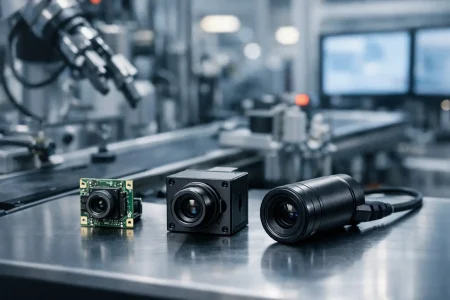
A solid example usually defines sensor resolution, frame rate, interface, lens field of view, shutter type, low-light behavior, and mechanical size. It should also state whether the module is intended for monocular navigation, stereo vision, visual SLAM, line following, docking, or sensor fusion with lidar and IMU.
A practical robot navigation camera module example
Consider a compact autonomous mobile robot designed for indoor logistics. The platform moves at moderate speed, operates under mixed warehouse lighting, and relies on visual SLAM plus short-range obstacle detection. In this case, a common camera module starting point would be a 2MP or 5MP MIPI camera module with a CMOS sensor, rolling or global shutter depending on motion speed, and a wide-angle lens in the roughly 120-degree range.
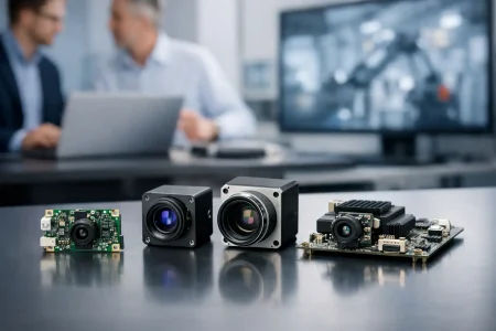
If the robot uses an embedded AI processor, MIPI is often the preferred interface because it supports high bandwidth with lower latency and lower board-level overhead than USB in tightly integrated systems. If the customer is still validating the vision algorithm on an x86 platform or development box, a USB camera module may speed prototyping. That does not mean USB is the final production choice. It simply reduces friction in the evaluation phase.
For the lens, wider is not always better. A very wide field of view helps with corridor awareness and near-field obstacle visibility, but it also introduces edge distortion and can reduce useful detail at distance. If the navigation stack depends on accurate feature extraction for mapping, lens selection should be matched to the operating distance and the calibration strategy.
In this example, a 2MP module running at 60 fps may outperform a 5MP module at 30 fps if the robot moves quickly and the processor has limited headroom. More pixels can improve map detail, but only if the downstream pipeline can process them consistently. Otherwise, the system pays for data it cannot use.
Sensor and shutter choices matter more than headline resolution
Buyers often begin with resolution because it is easy to compare. For navigation, shutter type and image stability usually matter more. A rolling shutter module can work well for slower indoor robots, especially when cost and availability are priorities. But if the platform turns quickly, moves over uneven surfaces, or captures motion-heavy scenes, rolling shutter artifacts can reduce feature tracking accuracy.
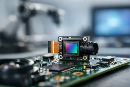
A global shutter module avoids that distortion by exposing the frame simultaneously. That typically improves visual positioning, marker reading, and motion estimation. The trade-off is cost, and sometimes lower pixel count or different power behavior depending on the sensor family.
Low-light performance is another frequent blind spot. Robots do not navigate only under lab lighting. They operate under warehouse sodium lamps, retail reflections, shadows near shelving, or early-morning ambient light through loading doors. A larger pixel size, tuned ISP behavior, and controlled noise performance can be more valuable than adding another few megapixels.
Interface selection affects the whole product roadmap
One reason camera module sourcing becomes difficult in robotics is that teams choose the interface too late. The interface is not just an electrical detail. It affects processing architecture, cable routing, EMI behavior, board design, and long-term manufacturability.
MIPI for embedded production platforms
MIPI camera modules are often the strongest fit for production robots using ARM-based compute boards, SoCs, or custom carrier boards. They support compact integration, high data throughput, and low latency. They also give engineers more room to optimize power and thermal performance in a tightly packed product.
The drawback is integration complexity. MIPI requires careful hardware matching, driver work, and system validation. It is usually the right production path, but not always the fastest route for a proof of concept.
USB for fast validation and flexible development
USB camera modules remain useful when the robotics team needs to test vision algorithms quickly, compare optics, or work with standard host systems. UVC compatibility can shorten early-stage software work and reduce setup time.
The trade-off is that USB can add bulk, power overhead, and connector limitations in compact mobile robots. It may be ideal for development and still be the wrong answer for mass production.
Mechanical design is part of the imaging decision
A navigation camera module does not live on a spec sheet. It lives behind a cover lens, near a motor, beside a battery, inside a heated enclosure, and often under constant vibration. That changes how the module should be selected.
Mounting position affects what the robot can actually see. A module placed too low may overemphasize floor texture and miss higher obstacles. A module placed too high may improve mapping range but create blind spots close to the chassis. The lens holder, FPC orientation, connector position, and board outline all matter once the ID and mechanical teams lock the enclosure.
This is why standard modules are often only the first step. In production robotics, teams frequently need adjusted FPC length, customized PCB dimensions, tuned lens angles, IR filter changes, or a specific connector arrangement to fit the final product. Customization is not cosmetic. It is how a workable prototype becomes a manufacturable design.
The real trade-offs in a robot navigation camera module example
No single module is best for every robot. The right choice depends on where failure is least acceptable.
If the platform needs high-speed motion tracking, global shutter may justify the added cost. If the robot is cost-sensitive and moves slowly in predictable lighting, a rolling shutter module may be sufficient. If the compute budget is tight, lower resolution with higher frame rate can be smarter than a bigger sensor. If software teams need quick iteration, USB may be the practical first step, even if MIPI is the production target.
The same logic applies to mono versus stereo. A single camera keeps cost and calibration effort lower. Stereo can improve depth perception, but it adds alignment requirements, processing load, and mechanical sensitivity. For some robots, lidar plus a single navigation camera is the more stable commercial choice.
How OEM teams should evaluate suppliers
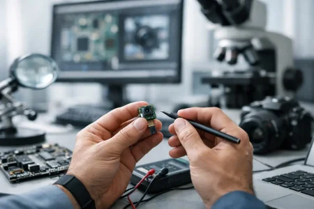
A strong robot navigation camera module example should not stop at image quality. It should show whether the supplier can support repeatable production. For robotics programs, supply quality includes sensor consistency, lens alignment control, connector reliability, ISP tuning support, and sample turnaround speed.
Engineering support also matters. Many projects do not need an off-the-shelf part alone. They need a module partner that can adjust optics, cable structure, board layout, and interface behavior around a specific compute platform. That is especially important when the robotics product is expected to scale from EVT to volume manufacturing without changing the imaging architecture midstream.
This is where a manufacturer with long optical and module integration experience has an advantage. SincereFirst works with standard and custom embedded vision modules for OEM devices that need stable performance, fast prototyping, and production readiness rather than a generic camera board.
Where this example leads in real development
The best robot navigation camera module example is not the one with the biggest sensor or the most marketing claims. It is the one that fits the robot’s motion profile, compute stack, enclosure limits, and production target from the start.
When imaging decisions are made early and with the full system in view, navigation gets easier to tune, not harder. That usually saves more time than any late-stage software patch. If you are building a robot that needs to see reliably before it can move confidently, the right camera module is less a component choice and more a design decision with consequences across the entire product.