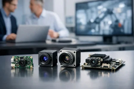
A camera that powers on but returns a black frame usually is not a sensor problem first. In embedded camera module troubleshooting, the fastest path is to stop treating the module as a single part and start checking it as a chain: power, clock, interface, driver, ISP, optics, and mechanics. That approach saves engineering time because most failures are not random. They usually come from one broken handoff between blocks.
For product teams building robotics, medical devices, handheld terminals, industrial inspection systems, or smart infrastructure, that distinction matters. A camera issue caught late can hold up EVT, delay regulatory testing, or force a board spin that costs far more than the module itself. The goal is not just to make the image appear. The goal is to identify whether the root cause sits in hardware, firmware, signal integrity, or optical integration so the fix is repeatable in production.
Start embedded camera module troubleshooting with the signal chain
A practical debug flow begins before you open the tuning tool or swap drivers. Verify whether the system can support the sensor at all. Confirm rail sequencing, inrush behavior, reset timing, master clock, and interface configuration. Then move upward into software enumeration, register programming, frame timing, and image quality.
This matters because similar symptoms can come from different causes. No image can mean missing AVDD, a disabled MCLK, a CSI lane mapping error, a wrong I2C address, or an ISP pipeline expecting an unsupported Bayer order. If teams skip steps and go straight to software, they often lose days on a hardware fault. If they start with hardware only, they may miss a simple driver mismatch.
Power and reset are still the first suspects
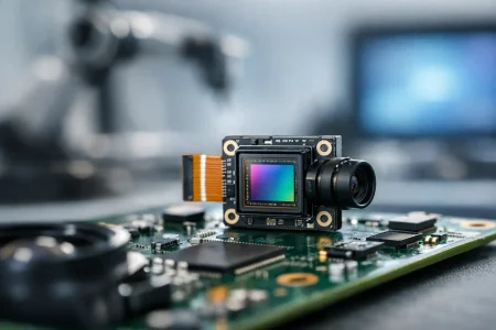
Most embedded camera failures begin at the rails. Many modules depend on multiple domains such as analog, digital core, and I/O, each with its own tolerance and sequence requirement. A rail that measures correctly at idle can still droop during startup or frame capture, especially on compact boards with shared regulators.
Check the actual voltage at the module connector or FPC, not just at the PMIC output. Long flex cables, marginal connectors, and thin traces can create a meaningful drop under load. Look at startup with an oscilloscope. Brownout events, overshoot, and delayed rise times regularly create intermittent behavior that looks like software instability.
Reset pins deserve the same attention. If PWDN or RESET timing does not align with the sensor datasheet, the module may answer on I2C but never stream video. Teams sometimes assume that partial communication means the camera is healthy. It does not. A sensor can acknowledge configuration writes and still remain in an invalid state because reset release, standby exit, or PLL lock timing was wrong.
Clock problems often hide behind black screens
A missing or unstable master clock is one of the fastest ways to get no frames. On MIPI and DVP designs, the sensor often needs a clean external clock before its internal timing blocks and serializers behave correctly. If the frequency is off, the duty cycle is poor, or the source has too much jitter, video startup can fail or become intermittent across temperature.
This is where board-level decisions matter. Route quality, clock source selection, and cross-talk from nearby switching rails all affect sensor behavior. A prototype may work on the bench and fail in low-temperature or high-EMI conditions because the timing margin was thin from the start.
Interface-specific faults change the debug path
MIPI CSI-2 modules
MIPI issues often look severe while the cause is basic. Lane count mismatches, incorrect lane polarity, swapped differential pairs, poor impedance control, and receiver timing settings can all stop image capture. Sometimes the camera streams, but the host cannot lock the data because settle time parameters or D-PHY settings are wrong.
A common trap is assuming that any module with the right connector will work if the sensor is supported. In reality, the host SoC may need exact lane mapping, virtual channel settings, clock mode compatibility, and a validated device tree entry. If one of those items is wrong, bring-up stalls even though the hardware is physically connected.
USB and UVC modules
USB modules simplify integration in many systems, but they are not immune to transport problems. If enumeration fails, start with cable quality, connector retention, VBUS stability, and EMI exposure. If the device enumerates but drops frames, inspect bandwidth allocation, host controller limitations, and compression settings.
UVC support helps with plug-and-play behavior, but it can also create assumptions. Standard compliance does not guarantee that exposure, trigger behavior, low-light tuning, or thermal performance match the application. If frame rate collapses at full resolution, the cause may be bandwidth and ISP configuration rather than the sensor itself.
DVP modules
DVP remains useful in cost-sensitive or legacy embedded platforms, but parallel buses are unforgiving about timing. Pixel clock polarity, HSYNC and VSYNC alignment, bit order, and drive strength all need to match the host. Even when the image appears, timing skew can create line tearing, color shifts, or unstable capture.
Software and driver issues are usually configuration issues
When power and signaling check out, software becomes the next layer. A large share of camera bring-up problems are not code defects in the classic sense. They are mismatches between sensor initialization tables, ISP expectations, and host-side media configuration.
Start by confirming basic communication. Can the host read the correct chip ID? Are initialization writes accepted? Are there hidden dependencies such as loading a register page before setting exposure or enabling streaming only after PLL configuration? Many sensors are sensitive to exact register order.
Then verify format alignment. Bayer pattern mismatch is a common example. The camera streams valid data, but the ISP interprets it as the wrong pattern, producing strange colors or poor demosaic behavior. Resolution, crop window, blanking, and frame timing also need to match every stage from sensor to application layer.
For Linux-based systems, device tree configuration, clock bindings, regulator definitions, and media graph routing frequently determine whether the camera appears at all. For RTOS or bare-metal systems, the risk shifts toward custom initialization code and timing assumptions. The point is the same: if the software stack describes a different camera than the one physically installed, the symptom can look like a dead module.
Image quality faults require a different mindset
Not every problem is a no-image event. Sometimes the module streams, but the output is unusable. Noise, blur, uneven shading, flicker, low dynamic range, and color instability demand a broader view because the root cause may be optical, mechanical, electrical, or algorithmic.
Focus problems are often integration problems. A lens can be correctly specified and still miss target distance because adhesive cure shifted the barrel, the housing stack changed the flange distance, or vibration affected retention. Fixed-focus modules are efficient in volume, but they need target working distance defined early. If the application range changes later, image quality will suffer even though the module passed initial testing.
Noise issues are also layered. Higher gain in low light increases visible noise, but so can poor grounding, rail ripple, or a hot enclosure near the sensor. Flicker may point to exposure settings under LED lighting rather than sensor failure. Smearing or washed highlights may come from the scene, lens flare, or an ISP tuning profile that does not fit the application.
Mechanical integration can break a good module
Engineers often debug the sensor and board while the real issue sits in the enclosure. FPC bend radius, connector stress, thermal expansion, and shielding contact can all affect field reliability. A camera that works during open-bench validation may fail after final assembly because the flex is over-bent or the module sits under constant torsion.
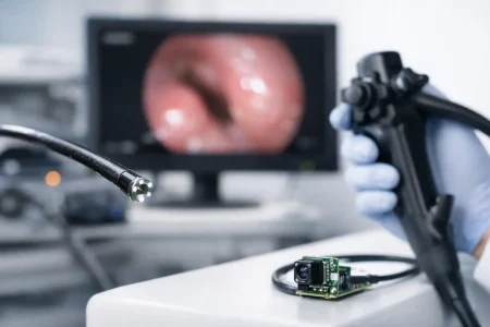
This is especially relevant in compact medical tools, robotics, and handheld industrial devices. Small mechanical changes can alter focus, introduce contamination risk, or create intermittent electrical contact. If failures appear only after assembly or drop testing, stop looking only at firmware.
Production problems are different from lab problems
One working prototype does not prove a stable design. In scaled manufacturing, the question changes from Can this camera work to How much margin does this design have across tolerance, temperature, and operator variation?
That is where disciplined embedded camera module troubleshooting pays off. If the debug process documents rail margin, connector tolerance, lens position control, interface eye margin, and software version control, production ramp becomes predictable. If not, the same symptom will reappear as random yield loss.
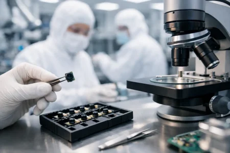
A serious manufacturing partner should help narrow that risk with verified reference designs, controlled optical assembly, cleanroom production, and fast sample iteration when a custom stack needs adjustment. For teams moving from prototype to volume, responsiveness matters almost as much as raw image performance.
What the fastest teams do differently
The most efficient teams isolate faults early and test one boundary at a time. They use known-good modules, known-good cables, and known-good firmware baselines before changing multiple variables. They capture rail waveforms, clock integrity, and interface behavior before editing long register tables. And they define the use case clearly, because a module tuned for barcode reading, endoscopy, machine vision, or face imaging will not behave the same under identical lighting.
That is also why custom support matters. Sensor choice, lens FOV, interface type, board stack-up, and ISP tuning all interact. A generic module may start the program, but if the final product has strict size, low-light, sterilization, or temperature requirements, troubleshooting gets easier when the module supplier understands both integration and mass production. SincereFirst works with OEM and device teams in exactly that gap between bench validation and deployable imaging hardware.
When a camera fails, the right question is not What broke first. It is Which interface between design blocks stopped transferring certainty. Solve that, and the image usually follows.