A pallet enters the receiving lane with a label that is wrinkled, partly covered by stretch wrap, and moving faster than the operator expected. That is the real test behind a warehouse scanning camera deployment example. The project is not won by selecting the highest-resolution sensor. It is won when the camera, lens, illumination, mechanical position, trigger logic, and warehouse software work together under real operating conditions.
For OEMs, automation integrators, and warehouse technology teams, a fixed scanning station can eliminate repetitive handheld scans, strengthen receiving traceability, and provide image evidence when a barcode cannot be read. The engineering challenge is to create a system that maintains read performance across label variation, package geometry, and shift-to-shift operating changes without introducing an unmanageable support burden.
Warehouse Scanning Camera Deployment Example: Receiving Lane
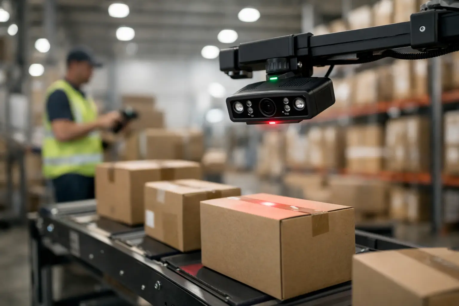
Consider a representative deployment at a high-volume distribution center. Cartons and pallets arrive through a receiving lane on powered conveyor. Each unit must be associated with an inbound shipment record by reading a GS1-128 barcode on a carton label or pallet placard. Some packages carry one label, while others may present labels on two adjacent faces.
The target throughput is 25 to 35 packages per minute. Cartons range from 10 to 48 inches wide, and label positions vary by several inches. The facility needs a read decision before the package reaches the diverter, while the warehouse management system needs the decoded value, timestamp, lane ID, and an image retained for exception review.
The solution uses two fixed industrial camera positions: one viewing the front face and one viewing the side face. A photoelectric sensor detects the package leading edge and sends a hardware trigger to both cameras. Images are processed at the edge computer, decoded locally, and passed to the warehouse software through the integrator’s selected industrial interface. Failed reads are routed to an exception station rather than stopping the line immediately.
This two-view layout costs more than a single camera, but it avoids forcing operators to orient every carton precisely. That trade-off is usually justified when labor variation and packaging inconsistency are bigger risks than camera hardware cost.
Start With the Read Zone, Not the Camera
The first engineering task is to define the read zone. Measure the maximum field of view, minimum and maximum package distance, expected label size, conveyor speed, and available mounting envelope. A camera specification without these values is only a starting point.
For example, a side-view station may need to cover a 48-inch-wide conveyor and read barcodes as small as 1.5 inches wide. The required pixel density depends on barcode symbology, print quality, and decoding algorithm, but the design team should calculate whether the narrowest expected code will occupy enough pixels for dependable decoding. More pixels can help, but they also increase processing load, bandwidth, memory requirements, and storage costs for retained images.
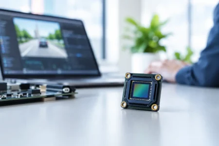
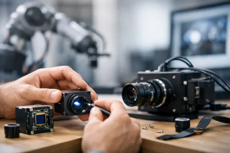
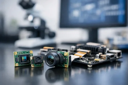
Lens choice is equally important. A wide-angle lens can cover a large lane but may create edge distortion and reduce effective barcode detail near the field boundary. A longer focal-length lens can improve pixel density but demands a greater working distance. Where the mounting height is constrained, a compact board camera with a carefully selected lens may fit where a larger housed unit cannot.
For custom systems, the camera module interface should match the compute architecture. MIPI CSI-2 modules suit compact embedded platforms with direct processor integration. USB 3.0 modules simplify connection to industrial PCs and can carry high-resolution images at practical frame rates. UVC USB cameras can shorten prototype cycles when standard driver support is valuable, although a production system still needs to validate cable length, bandwidth sharing, and device recovery behavior.
Lighting Decides Whether the Barcode Exists
A barcode may look clear to the human eye and still produce poor image contrast. Glossy labels, thermal print variation, shrink wrap, and overhead LEDs can all create reflections that interrupt bars or modules in the image.
In this deployment, diffuse LED illumination is installed above and to each side of the read zone. The lighting is positioned to reduce direct reflections into the lens, not simply to make the lane brighter. A short, controlled exposure freezes package motion. If ambient daylight reaches the dock, the enclosure or shroud should be designed to limit changing light conditions.
There is no universal lighting geometry. Dark cartons with white labels often respond well to diffuse white light. Reflective films may need angled lighting or polarization. Direct lighting can produce sharper contrast on some printed surfaces, yet it is less tolerant of label wrinkles and glare. The correct decision comes from testing actual packaging samples, including poor samples that receiving teams see every week.
Triggering and Motion Control
Free-running video is possible, but hardware triggering provides a more predictable inspection event. The photoelectric sensor identifies the package position, and the camera captures at a known offset. If conveyor speed changes, the control system can adjust the trigger delay or use encoder data to maintain image timing.
Motion blur must be calculated, not guessed. At a fast conveyor speed, a long exposure can smear barcode edges enough to reduce decoding success even when the image appears acceptable on a dashboard. Higher illumination permits shorter exposures. Global shutter sensors are often preferred for moving-package applications because they capture the full frame at the same instant. A rolling shutter module may be suitable for slower lines or controlled movement, but it should be validated at the actual operating speed.
The station should also account for package gaps. If two cartons travel close together, the triggering logic needs rules that prevent one package from being associated with the next package’s image. This is where a camera deployment becomes part of the material-handling control design rather than a standalone imaging purchase.
Edge Processing and Warehouse System Integration
At the edge computer, the software performs barcode detection, decoding, confidence scoring, and image quality checks. The application then sends a result to the WMS, WES, PLC, or middleware layer. A useful result packet includes the decoded ID, read status, camera ID, lane ID, capture time, package tracking reference, and image reference.
The failure path deserves as much attention as the successful read path. If neither camera produces a valid code, the system can request a rescan, signal a stack light, divert the package, or present the saved images to an operator. The right action depends on line speed and the cost of a missed inbound record. High-throughput facilities often prefer controlled diversion; lower-volume operations may use an operator confirmation screen.
Image retention must be specified early. Keeping every full-resolution image indefinitely can become expensive. Many deployments retain images for a limited period, save only exceptions at full resolution, or archive compressed evidence images after a successful read. The policy should align with quality, customer dispute, and data-security requirements.
Validate Against Warehouse Reality
A bench test with clean labels is useful for initial optics work, but it is not deployment validation. The acceptance plan should include different carton colors, damaged labels, skewed cartons, glossy wrap, multiple barcode formats, partially blocked codes, and the fastest expected conveyor speed.
Track more than the headline read rate. Teams should measure first-pass read rate, total read rate after approved retries, false-read rate, image-to-result latency, exception rate by supplier or label type, and recovery behavior after a cable or power interruption. A 99.5% read rate can be excellent or insufficient depending on whether the facility processes 5,000 packages per day or 500,000.
Mechanical durability also matters. Mounts should resist vibration, cable routing should protect connectors from snagging, and the optical window should be accessible for cleaning. A camera positioned perfectly on commissioning day can drift after repeated impacts from nearby equipment if the bracket is underspecified.
From Pilot Station to Repeatable Deployment
Once the first lane meets its targets, document the approved camera distance, lens setting, illumination angle, trigger parameters, software version, exposure range, and installation tolerance. This turns a successful pilot into a repeatable deployment package for other facilities.
SincereFirst supports this type of program with standard and customized camera modules, including MIPI and USB options, matched to the embedded processor, optical envelope, and production requirements of the finished scanning system. For an OEM, early alignment on sensor selection, lens integration, interface, and manufacturing test criteria can prevent late redesigns when the project moves from prototypes to volume builds.
The best warehouse scanning station is not the one with the most impressive lab image. It is the one that keeps reading imperfect labels on a busy dock, provides a clear exception path when it cannot, and can be reproduced accurately on the next hundred lanes.