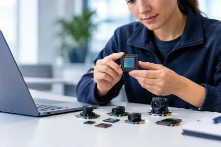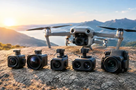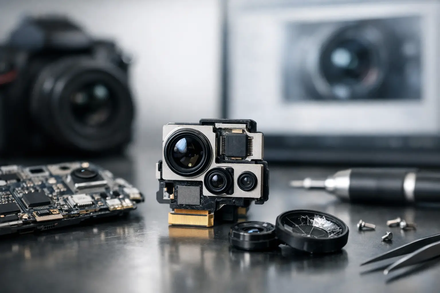
A camera module can pass initial bring-up, deliver a clean image on the bench, and still fail after a few weeks of vibration, thermal cycling, handling, or field use. That is why do camera modules fail is not just a component-quality question. For OEMs and system integrators, it is a system engineering question that spans optics, electronics, mechanics, firmware, assembly, and supplier process control.
The visible symptom – no image, unstable streaming, haze, color shift, lines, or intermittent detection – rarely identifies the true failure mechanism by itself. A disciplined root-cause process is the fastest way to protect production yield, warranty cost, and device uptime.
Why Do Camera Modules Fail in Commercial Devices?
Most failures occur where design margins are thin or where interfaces are treated as independent. A sensor may be qualified, a lens may meet specification, and an FPC may pass continuity testing, yet the assembled module can still become unreliable when installed in the final product.
The highest-risk conditions are usually heat, mechanical stress, contamination, signal integrity loss, and inconsistent assembly. The exact priority depends on the application. A fixed indoor security camera faces different risks than a robotic camera exposed to motion, or a miniature endoscope module operating in a tightly constrained medical or industrial instrument.
1. Optical contamination and poor lens protection
Dust, fingerprints, adhesive vapor, moisture residue, and particles inside the optical path can reduce contrast or create visible spots and flare. This is especially damaging in small-format modules because a tiny contaminant can occupy a meaningful portion of the image area.
Contamination is not always introduced at final assembly. It can enter during lens installation, sensor bonding, rework, packaging, or the customer’s device-level integration process. In modules with autofocus, IR-cut filters, or protective windows, each added optical surface creates another place for particles, reflections, and alignment errors to affect image quality.
Cleanroom discipline, controlled material storage, proper protective films, and inspection under representative illumination reduce this risk. For products used outdoors or in harsh environments, the camera design should also consider enclosure sealing, venting strategy, and the coating or treatment of the external cover glass.
2. Lens-to-sensor misalignment
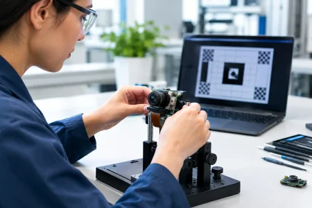
A lens that is slightly tilted, decentered, or positioned at the wrong working distance can produce corner blur, uneven sharpness, focus variation, or distortion beyond the intended specification. At high resolution and with small pixel sizes, tolerances become more demanding. What looks acceptable in a center-field inspection may fail when the full image field is evaluated.
Mechanical shock and temperature changes can also shift components after assembly. Adhesive selection matters because cure shrinkage, long-term creep, and coefficient-of-thermal-expansion mismatch can change alignment over time. A reliable module needs controlled active alignment or an equivalent precision process, followed by image-quality verification that reflects the intended working distance and field of view.
3. Sensor damage from ESD, heat, or electrical overstress
Image sensors are sensitive semiconductor devices. Electrostatic discharge can cause immediate failure, latent damage, increased dark current, dead pixels, or unstable behavior that only appears after deployment. Electrical overstress from incorrect power sequencing, voltage spikes, reverse connection, or inadequate grounding can create similar symptoms.
Thermal exposure is another concern. Reflow limits, nearby processors, LEDs, and enclosed product housings can push the sensor or supporting circuitry beyond its design margin. Higher operating temperature may increase noise, hot pixels, and image instability even when the module continues to function.
ESD-safe workstations, validated power sequencing, transient protection, and realistic thermal testing are essential. Engineering teams should test the module in the final mechanical enclosure, not only on an open evaluation board where heat dissipates more easily.
4. MIPI, USB, or DVP signal integrity problems
Many apparent camera failures are actually interface failures. MIPI CSI-2 modules can show frame drops, corrupted images, intermittent startup, or no detection when differential pair routing, impedance control, grounding, clock configuration, or lane mapping is incorrect. USB camera modules may be affected by cable quality, voltage drop, electromagnetic interference, host compatibility, or insufficient power from the port.
The module may pass at a short cable length in the lab and fail in a production device with a different harness route, longer FPC, switching power supply, or motor nearby. This is why interface validation must include the actual cable or FPC, host processor, firmware version, and operating conditions.
For custom designs, specify the interface early: MIPI, USB 2.0, USB 3.0, DVP, or another required architecture. Interface choice affects bandwidth, cable length, power design, software effort, and mechanical packaging. Selecting a high-resolution sensor without confirming end-to-end bandwidth is a common and avoidable failure path.
5. FPC, connector, and solder-joint fatigue
Compact camera modules often depend on fine-pitch FPCs and connectors that experience bending, insertion force, vibration, and repeated assembly handling. A cracked trace, partially seated connector, weak solder joint, or damaged contact can cause intermittent image loss that is difficult to reproduce.
This risk increases in robotics, handheld equipment, vehicles, portable diagnostics, and equipment with moving heads or articulated arms. Flex design needs an appropriate bend radius, strain relief, stiffener placement, and routing path. The final product should prevent sharp folds and avoid transferring enclosure stress directly to the module connector.
Connector selection is not a minor purchasing detail. Contact plating, retention force, mating-cycle rating, pin pitch, and supplier consistency all affect field reliability. Inspection should include continuity and image streaming tests after mechanical cycling, not before it alone.
6. Moisture ingress and environmental exposure
Humidity can cause corrosion, fogging, leakage current, adhesive degradation, and failure of unprotected electronics. In outdoor, agricultural, medical, and industrial applications, modules may also encounter cleaning agents, oil mist, dust, salt air, or sudden temperature changes that create condensation.
A camera module is only as protected as the full imaging assembly. An IP-rated enclosure may still fail if the lens window seal is weak, pressure changes draw moisture inward, or a cable exit is poorly designed. Conformal coating can help in some electronics areas, but it must not contaminate optics, interfere with moving parts, or trap moisture.
Environmental validation should be application-specific. A warehouse robot, a surgical visualization device, and a smart-city camera require different test profiles. Generic temperature testing is useful, but it cannot replace testing against actual exposure conditions.
7. Firmware, driver, and calibration mismatch
A good module can appear defective when its sensor register settings, driver, image signal processor tuning, or calibration data do not match the host platform. Symptoms may include incorrect color, low frame rate, rolling artifacts, exposure hunting, image inversion, or a module that fails to initialize consistently.
Sensor changes are particularly risky when a procurement substitution is made without full validation. Two modules may share resolution, interface, and physical dimensions while requiring different clocking, power sequencing, lens shading correction, or auto-exposure tuning. A pin-compatible replacement is not automatically software-compatible.
Control this risk through documented module revisions, approved firmware versions, configuration management, and clear ownership of image tuning. For computer vision applications, validate not only visual image quality but also downstream detection accuracy across real scenes and lighting conditions.
8. Inadequate incoming inspection and process control
Some failures originate before the module reaches final assembly. Variation in sensors, lenses, adhesives, connectors, or subassemblies can raise defect rates if lot traceability and incoming quality controls are weak. Rework can add another layer of risk, particularly when it exposes optics or fine-pitch electronics to excess heat and handling.
A capable manufacturing partner controls the process from material qualification through optical assembly, electrical test, image inspection, aging, and shipment packaging. For high-volume programs, the goal is not simply to catch defective units. It is to understand process capability well enough to prevent variation from reaching the line.
SincereFirst supports this approach through engineering-led module customization and scaled production controls, helping teams align sensor selection, optical requirements, interface design, and manufacturing validation before volume ramp.
Preventing Camera Module Failures Before Production
The most effective preventive action is early cross-functional review. R&D, mechanical design, embedded software, quality, and sourcing teams should evaluate the module as part of the finished device. Review heat paths, FPC routing, connector access, power-up behavior, image requirements, environmental exposure, and service conditions before tooling is released.
Build validation around failure mechanisms rather than a generic checklist. Test image quality after vibration and thermal cycling. Check startup reliability across voltage and temperature limits. Measure interface performance with the final host and cable assembly. Inspect for contamination after environmental testing, not just immediately after manufacturing.
A camera module should be selected for the conditions it will actually face, not only for its data-sheet resolution or unit cost. When optical precision, electrical integration, and production discipline are treated as one engineering system, camera reliability becomes a design outcome rather than a warranty surprise.
The practical next step is to define your operating environment and acceptance criteria before requesting samples. That gives the camera supplier a clear basis to recommend the right sensor, lens, interface, mechanical structure, and validation plan for dependable production.