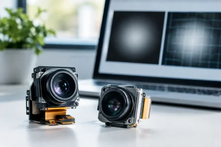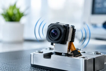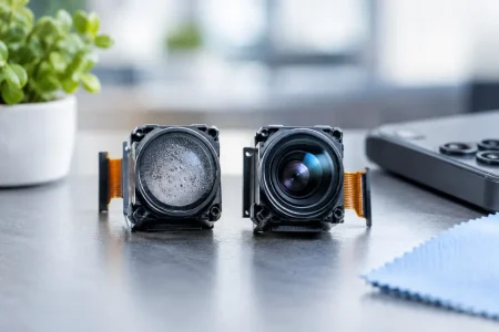

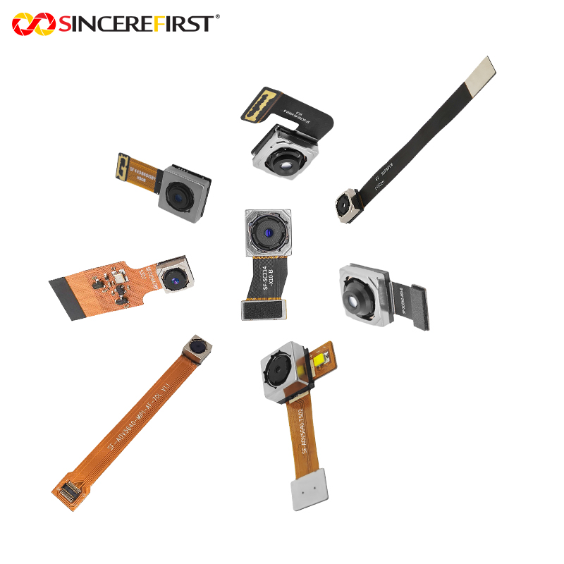

A camera can stream a clean image on an engineering bench and still fail when the production cable, host board, temperature, or frame rate changes. To validate MIPI CSI lanes properly, teams must prove more than basic image output. They need evidence that the physical link, CSI-2 packet stream, host receiver, and selected camera mode remain stable at the limits the finished device will actually face.
For OEM camera integration, this work should begin before design verification testing. Finding a lane-routing, clocking, or receiver-configuration fault after a board build can cost weeks of rework and put a product schedule at risk. A structured validation plan turns MIPI CSI-2 bring-up from a visual check into a measurable engineering gate.
Define What a Passing MIPI CSI Link Looks Like
Start with the intended operating point: sensor resolution, frame rate, bit depth, pixel format, number of data lanes, lane rate, cable or FPC length, and host processor. These values determine whether the interface has adequate bandwidth and whether the design needs a two-lane or four-lane configuration.
A useful first calculation is the approximate payload requirement:
`horizontal pixels × vertical pixels × frames per second × bits per pixel`
The actual link requirement is higher because CSI-2 transport includes packet overhead, line and frame blanking behavior, and margin for timing variation. A design that appears to fit precisely on paper may show dropped frames when exposure settings, frame timing, or software processing changes. Specify a practical headroom target with the sensor and host configuration in mind rather than designing to the theoretical limit.
Document the acceptance criteria before testing. For example, a production-ready link may need to operate at the target lane rate with zero uncorrectable packet errors, no frame loss over an extended run, stable performance across the specified supply range, and repeatable start-up after power cycling. The criteria should also define image-level checks such as correct resolution, color order, bit depth, and exposure behavior.
Inspect the Physical Path Before Power-On
MIPI CSI-2 commonly uses the D-PHY physical layer, with a differential clock pair and one or more differential data pairs. These signals transition between low-power signaling and high-speed signaling, so continuity alone does not validate the interconnect. The route must preserve differential impedance, pair coupling, return-current continuity, and skew control from the camera module connector to the host receiver.
Review the schematic and layout against the host SoC guidance and the selected camera module requirements. Check that data pairs have not been swapped unintentionally, that the clock pair reaches the intended receiver pins, and that lane numbering is consistent across the sensor, FPC, connector, and processor documentation. Connector drawings can use a different viewing direction than board layouts, making mirrored pinouts a common and expensive error.
Pay close attention to discontinuities. Unnecessary test pads, stubs, poorly referenced vias, sharp return-path interruptions, and connector transitions can degrade the high-speed channel. The allowable margin depends on the selected lane rate, stack-up, trace length, and PHY capability. A short two-lane mobile camera route may tolerate a layout that becomes unreliable when applied to a longer FPC or a four-lane industrial design.
Where the project risk justifies it, use TDR or channel simulation before hardware release, then confirm the built board with measurement. Also inspect FPC insertion quality, connector latch engagement, ground-pin contact, and cable bend condition. Many intermittent camera faults originate in the mechanical path rather than in the image sensor.
Bring Up Lane Mapping and Sensor Timing
The first powered test should use a known-good sensor register configuration, a known-good host receiver driver, and a controlled camera mode. Avoid changing resolution, lane count, PLL settings, and receiver timing parameters at the same time. Isolating variables makes failures diagnosable.
Confirm that the sensor is powered and reset in the required sequence, that its reference clock is present, and that I2C control communication is reliable. A sensor may answer I2C transactions while its MIPI transmitter remains disabled or configured for a different output mode. Verify the sensor output format, virtual channel, data type, lane count, and lane-rate setting directly from the register configuration.
At the receiver, verify the configured lane map and polarity settings. Some hosts support data-lane polarity inversion in software; others do not. Clock-lane reversal and data-lane ordering are not interchangeable settings. Treat each as a deliberate, documented hardware-to-software mapping.
The most frequent configuration errors include:
- Selecting a two-lane sensor mode while the host expects four lanes
- Assigning data lane 0 and data lane 1 in the wrong order
- Configuring an incorrect CSI-2 data type or pixel packing format
- Using receiver settle timing that does not match the sensor lane rate
A preview image is a useful signal, but it is not sufficient proof. Incorrect Bayer order, truncated lines, periodic corruption, or missing metadata can remain hidden if the application pipeline converts, crops, or compresses the stream before it is inspected.
Measure D-PHY Behavior at the Actual Lane Rate
To validate MIPI CSI lanes electrically, capture the clock and data pairs with equipment that has suitable bandwidth, probing method, and differential measurement capability. The objective is not merely to see high-speed activity. Measure behavior against the applicable D-PHY requirements and the host receiver’s tolerance at the deployed rate.
Observe both low-power and high-speed transitions. Check for clean entry to high-speed mode, valid clock behavior, expected data bursts, excessive ringing, amplitude problems, common-mode disturbance, and timing instability. A poor probe connection can alter a sensitive signal, so use an appropriate fixture or probing method and record the setup with the result.
Eye-diagram analysis, when available, provides stronger evidence than a single waveform capture because it reveals variation across many transitions. Compare the measured result to the relevant PHY limits and to the margin required by the host platform. Do not assume that a signal passing on one prototype will pass after a display cable, RF subsystem, metal enclosure, or alternate FPC is added.
If the design uses C-PHY rather than D-PHY, apply a separate test plan. C-PHY uses three-wire trios and different signaling and measurement assumptions. A D-PHY validation method cannot simply be reused because both interfaces carry CSI-2 traffic.
Verify CSI-2 Packets, Not Just Pixels
The CSI-2 protocol layer provides another critical validation point. Use host-side counters, kernel logs, receiver diagnostics, or a protocol analyzer to inspect frame start and frame end packets, line behavior, long-packet payloads, virtual-channel values, data types, ECC events, and CRC errors.
ECC correction events deserve attention even when frames appear acceptable. A corrected header fault may indicate shrinking electrical margin, an unstable connector, or an early layout problem. CRC errors, FIFO overflows, receiver timeouts, and frame-sync mismatches should be treated as engineering failures until their source is understood.
Test the actual formats the product will ship. RAW10, RAW12, YUV, RGB, embedded data, multi-camera virtual channels, and high dynamic range modes can create different packet patterns and bandwidth demands. A link that is stable in a low-resolution preview mode may fail as soon as the final production mode enables full resolution and embedded metadata.
Stress the Complete Camera Pipeline
Long-duration testing exposes faults that short bench captures miss. Run continuous streaming at the highest approved resolution and frame rate while cycling sensor resets, entering and leaving standby, restarting the host application, and repeating power cycles. Test at temperature limits where possible, because sensor PLL behavior, FPC characteristics, and host timing margins can shift.
Also test the system under realistic processor load. An AI accelerator, display output, storage write, Ethernet transfer, or second camera stream can expose bandwidth contention outside the MIPI physical link. Separate CSI receiver errors from ISP, memory, driver, and application failures, but validate the entire image path before approving the design.
For multi-camera products, start cameras in different orders and test synchronized and unsynchronized operation. Confirm that each module retains its intended I2C address, virtual channel, frame timing, and lane allocation. This is especially relevant for robotics, medical devices, inspection equipment, and smart infrastructure systems where a lost stream may affect system decisions.
Turn Validation Results Into a Production Control Plan
A successful prototype test is only valuable if it can be repeated across builds. Preserve the sensor configuration file, host driver version, board revision, cable part number, test mode, measurement screenshots, packet-error logs, and pass/fail thresholds. These records give purchasing, manufacturing, and field-support teams a clear reference when substitutions or revisions are proposed.
For custom camera assemblies, control the module connector, FPC stack-up, lens holder, shielding approach, and test fixture as part of the released configuration. An optical change or mechanical adjustment can affect the electrical channel. SincereFirst supports this process by aligning camera module selection, MIPI interface configuration, FPC design, and production testing with the target host platform rather than treating the camera as an isolated component.
The practical goal is confidence under the conditions that matter: every approved camera mode, every specified environmental condition, and every planned production build. When lane validation is treated as a measurable release gate instead of a quick image check, the camera interface becomes far less likely to become the last unresolved problem before launch.