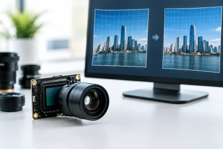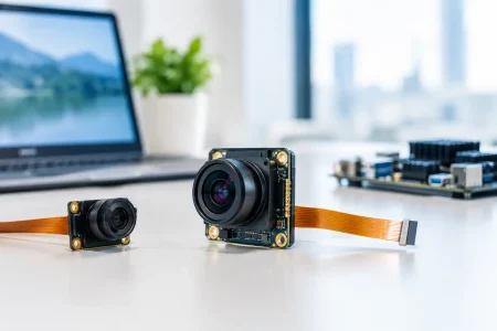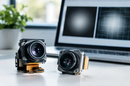

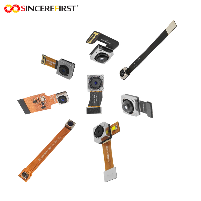
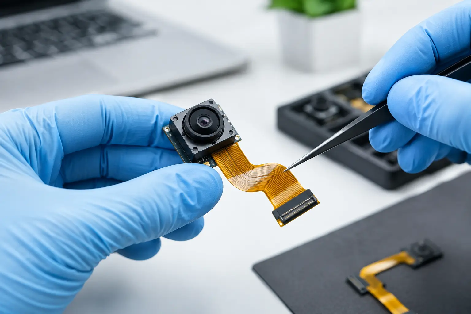
A camera module can pass image qualification on the bench and still fail when installed in the final product. The usual difference is not the sensor. It is the flex path: a longer FPC, a noisy display, a switching regulator, a motor, or a ground return that changed during mechanical integration. To reduce FPC signal interference, engineers must treat the cable, connector, PCB, and enclosure as one electrical system rather than separate parts.
This matters most for compact MIPI CSI-2 camera modules, where high-speed differential lanes run beside power, control, and sometimes LED or actuator lines. A small layout compromise can create intermittent image artifacts, dropped frames, link instability, or compliance problems that only appear in specific operating modes.
Why FPC camera signals become vulnerable
An FPC is not simply a convenient interconnect. At high frequencies, every trace has impedance, coupling behavior, insertion loss, and a return-current path. The electrical effect depends on flex length, layer construction, trace geometry, bend location, connector transitions, and nearby noise sources.
MIPI D-PHY signals are differential, which provides meaningful common-mode noise rejection. That does not make them immune to interference. Noise becomes a problem when the pair is imbalanced, when return paths are interrupted, when impedance changes sharply, or when external coupling is converted into differential noise. Clock lanes and high-speed data lanes are particularly sensitive to discontinuities at connectors, vias, shielding transitions, and stiffener edges.
The camera module also contains analog functions. Sensor supplies, reference circuits, clock sources, I2C control lines, and autofocus or LED drivers can contribute noise. A design may therefore show both signal-integrity symptoms and image-quality symptoms, including horizontal bands, fixed-pattern noise changes, color instability, or failures during motor operation.
Start with the interface and bandwidth budget
The first design decision is whether the FPC architecture is appropriate for the selected sensor output. Higher resolution, frame rate, bit depth, and number of MIPI lanes all increase the margin required from the interconnect. A short two-lane FPC for a standard 1080p module does not automatically scale to a long cable carrying a high-frame-rate, multi-megapixel stream.
Define the required lane rate, FPC length, connector type, bend radius, operating temperature, and nearby aggressors before releasing mechanical design. This avoids a common late-stage issue: selecting a camera module that performs correctly with a short evaluation cable, then extending the same interface through a narrow product hinge or moving assembly.
For some applications, the right answer is a shorter FPC and a relocated processor board. For others, a different interface, additional MIPI lanes at a lower rate per lane, or a serializer-based architecture may offer more margin. There is no universal cable length limit because stackup quality, receiver capability, and system noise determine the practical result.
Reduce FPC signal interference with controlled impedance
Controlled impedance is the foundation of reliable high-speed FPC performance. The differential pair geometry must be designed around the actual flex stackup, including copper thickness, dielectric thickness, coverlay, adhesive layers, and reference plane. Nominal trace width alone is not enough.
For MIPI differential pairs, maintain the specified differential impedance across the full flex length. The target value is commonly defined by the chipset and interface requirements, often near 100 ohms differential, but the design should follow the applicable component documentation and measured stackup rather than assumptions. A flex supplier should provide impedance modeling and production verification for the approved construction.
Keep each differential pair tightly coupled and geometrically consistent. Sudden changes in trace width, spacing, copper environment, or reference-plane distance cause reflections. Avoid routing a high-speed pair across a split in the ground plane, because return current must then find an indirect path. That increases loop area and makes the link more susceptible to radiated and conducted noise.
Pair length matching also matters, although excessive tuning can create its own problems. Long serpentine sections add loss and coupling. Use the shortest practical compensation pattern, keep tuning sections away from aggressors, and follow the maximum intra-pair skew specified by the MIPI receiver and camera sensor.
Separate noisy power and sensitive lanes
Many interference failures begin with power routing, not data routing. Switching converter ripple, display supply transients, PWM LED currents, and motor drive pulses can couple into FPC conductors through electric and magnetic fields. If a camera shares a flex with a display, touch panel, infrared LED, or autofocus actuator, partitioning becomes essential.
Place ground conductors or ground planes between high-speed camera lanes and noisy power lines wherever the stackup allows. Do not run a switching-node trace, boost-converter output, or pulsed LED supply parallel to MIPI lanes over a long distance. If the routing must coexist, increase separation and provide a continuous ground shield between the circuits.
Camera power should be filtered close to the module, with the exact network chosen for the sensor and module design. A ferrite bead may help isolate high-frequency noise, but it is not a substitute for correct grounding or stable regulation. Beads can also create unwanted resonances when paired with capacitors, so validate the complete power distribution network rather than adding components after a problem appears.
I2C lines are slower than MIPI lanes but can still cause operational failures when they pick up noise or have poor pull-up sizing. Keep control traces away from high-current switching paths and ensure the logic-voltage domain, pull-up voltage, and level-shifting arrangement are compatible with the camera module.
Use grounding and shielding as a system
A continuous ground reference under high-speed traces is more valuable than a cosmetic shield can. Ground should provide a low-inductance return path from the processor to the camera module and through every connector transition. If the FPC includes multiple ground traces, distribute them strategically beside high-speed pairs and around sensitive control lines.
Grounding becomes more complicated when the module is mounted in metal equipment, medical instruments, or industrial housings. Chassis ground and signal ground may need a deliberate connection strategy to control emissions without injecting external noise into the camera reference. The correct approach depends on the enclosure, power source, cable exposure, and regulatory environment.
Shielding can be effective when the FPC travels near a display, radio antenna, motor, or switching supply. Options include shielded FPC construction, conductive tape, grounded copper foil, or a conductive enclosure feature. However, shielding only works when it is properly terminated. A floating shield may offer limited benefit, while an improperly connected shield can create capacitance or antenna effects that complicate the design.
Avoid placing the FPC directly over inductors, DC-DC converters, antenna feed structures, or high-current traces. Mechanical teams should understand these keep-out zones early. A few millimeters of relocation can solve an issue that hours of firmware tuning will not.
Protect connector transitions and mechanical reliability
Connectors are frequent weak points in a camera signal path. Select a connector with adequate high-speed performance for the lane rate and ensure its pin assignment supports clean grounding. Ideally, high-speed pairs should have nearby ground references rather than being grouped beside power or low-speed lines without isolation.
Keep connector traces short and avoid unnecessary layer changes on the host PCB. Where vias are required, use symmetric via structures for each member of the differential pair and minimize stubs. Poorly matched breakout routing can negate an otherwise well-designed FPC.
Mechanical reliability is also electrical reliability. Repeated bending can alter conductor geometry, crack shielding layers, stress solder joints, or damage the flex near a stiffener. Route the dynamic bend area away from the most sensitive high-speed section when possible. Maintain the FPC supplier’s bend-radius requirement and avoid sharp folds during assembly.
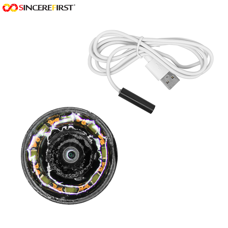
For endoscope, robotics, and other moving applications, test the complete camera assembly through realistic motion cycles. Interference may appear only when the flex changes position relative to a motor, metal frame, or RF source. Electrical qualification without mechanical cycling leaves this failure mode unresolved.
Validate the complete camera integration
A design review is necessary, but measurement is decisive. Validate with the final-length FPC, production-intent connector, representative enclosure, display, wireless radios, power supply, and motion components active. Testing a camera module on an open bench cannot fully represent the deployed electromagnetic environment.
Start with functional image checks under different loads: display brightness changes, radio transmit activity, motor operation, charging, and thermal transitions. Then inspect MIPI error counters, frame loss behavior, and sensor register communication. Oscilloscope and protocol analysis can help identify timing, power, or link failures, while eye-diagram and impedance measurements provide deeper evidence when margin is tight.
A useful troubleshooting sequence is to isolate the source before changing the design. Temporarily power the camera from a quiet supply, disable nearby switching loads, shorten the FPC, add a grounded shield, or change cable position. Each controlled change reveals whether the dominant issue is conducted noise, radiated coupling, signal loss, return-path discontinuity, or mechanical stress.
For OEM programs, involve the camera module supplier before the host PCB and industrial design are frozen. SincereFirst can support this process with FPC camera module selection, pinout alignment, optical and mechanical customization, and production-oriented integration review. Early engineering coordination is faster and less costly than redesigning a finished enclosure or a high-volume PCB.
The best FPC design is not the one with the most shielding or the widest spacing. It is the one that preserves impedance, return paths, power integrity, and mechanical stability within the real product constraints. Build those decisions into the first prototype, and the camera system will have the margin needed to perform consistently beyond the lab.