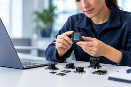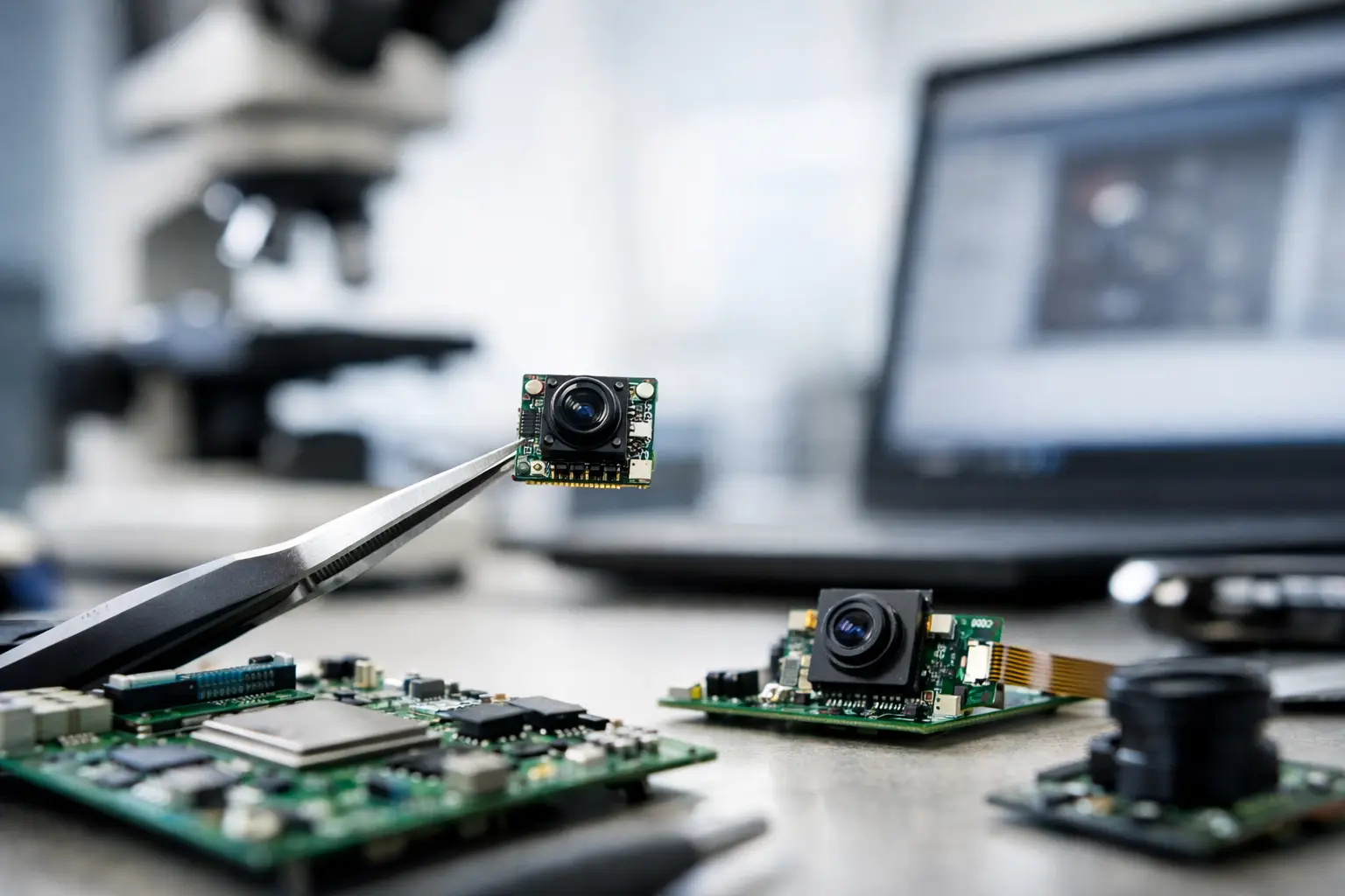
A camera module that works on an evaluation kit can still fail inside a finished product. The usual causes are not the sensor alone. A constrained flex route, noisy power rail, poorly matched lens, or an untested ISP pipeline can turn a promising image into dropped frames, color errors, or inconsistent production yield. Knowing how to design board level camera integration means treating the camera, host board, mechanics, and image software as one engineered system.
For product teams building robotics, medical devices, security equipment, agricultural systems, or industrial automation products, the objective is clear: specify an imaging architecture that meets the required image quality and latency while remaining manufacturable at volume. That requires decisions made in the right order.
Start With the Image Requirement, Not the Camera Module
The fastest way to create rework is to select a camera by resolution alone. Start instead with the scene the device must capture. Define the working distance, field of view, target size, lighting condition, motion speed, acceptable blur, required frame rate, and the details that must be recognized or measured.
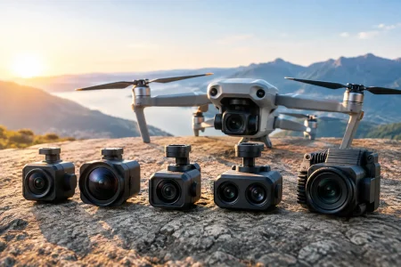
A warehouse robot may need low-latency wide-angle imaging for navigation. An inspection station may need controlled illumination, high pixel density, and low distortion for measurement. A medical imaging device may prioritize small diameter, consistent color reproduction, and low heat. Each requirement leads to a different sensor, lens, interface, and mechanical arrangement.
Translate those needs into measurable targets before requesting samples. Useful specifications include active resolution, pixel size, shutter type, sensitivity, dynamic range, signal-to-noise ratio, modulation transfer function, and camera-to-application latency. If the output will feed an AI model, also verify the model’s required input resolution, color format, exposure behavior, and frame timing. A high-resolution sensor does not improve a model trained on lower-resolution, motion-blurred images.
Choose the Sensor and Shutter for the Actual Scene
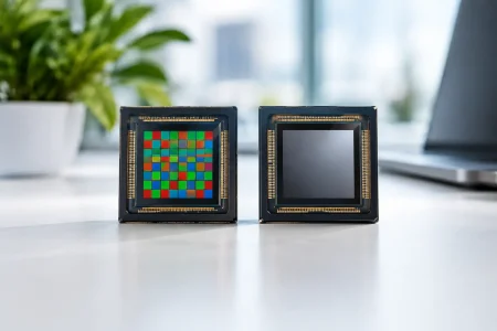
Sensor selection is a compromise between image quality, power consumption, module size, interface bandwidth, and cost. Larger pixels generally help in low light, but they increase sensor size or limit resolution. Higher resolution can preserve fine detail, but it raises bandwidth, memory use, processing load, and thermal output.
The shutter decision is particularly consequential. A rolling shutter is compact, economical, and suitable for many static or moderately moving scenes. However, fast motion, vibration, rotating parts, or rapidly changing illumination can produce skew and banding. A global shutter captures the full frame at the same instant and is often the better choice for machine vision, barcode reading, robotic guidance, and high-speed inspection. It may require a larger budget or involve trade-offs in resolution and low-light performance.
Also decide whether the sensor should output RAW Bayer data, YUV, or compressed video. RAW preserves the greatest tuning flexibility and is often preferred where the host ISP can be controlled. YUV output can simplify host integration when image processing is handled within the module or sensor pipeline. Compressed output reduces transport bandwidth but may be unsuitable for measurement, post-processing, or applications sensitive to compression artifacts.
Match the Lens to the Sensor, Not Just the Housing
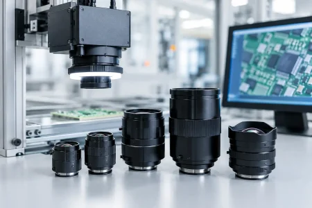
The lens must cover the sensor’s image circle and support the required field of view at the chosen working distance. A lens that is physically compatible can still create corner shading, poor edge sharpness, or unwanted distortion. Verify focal length, F-number, chief ray angle tolerance, distortion, focus range, and infrared response.
Fixed-focus modules work well when the target distance is controlled. Auto-focus is useful for handheld or variable-distance products, but it adds moving parts, control requirements, focus time, and qualification work. For inspection systems, a carefully set fixed-focus lens is often more repeatable than auto-focus.
Lighting belongs in the optical decision as well. Sensor gain cannot recover detail that poor illumination never captured. Consider the illumination spectrum, reflections, flicker frequency, and whether visible, infrared, or mixed lighting is required. If infrared LEDs are used, specify the appropriate IR-cut filter strategy to avoid inaccurate daytime color or weak night performance.
Select an Interface That the Host Can Sustain
MIPI CSI-2 is commonly selected for compact embedded products because it delivers high bandwidth with low pin count and supports direct connection to many application processors. It is often the right choice for smartphones, tablets, robotics controllers, and custom embedded boards. Its limitation is distance: the high-speed differential lanes must be routed carefully, and long flex cables or electrically noisy environments need added attention.
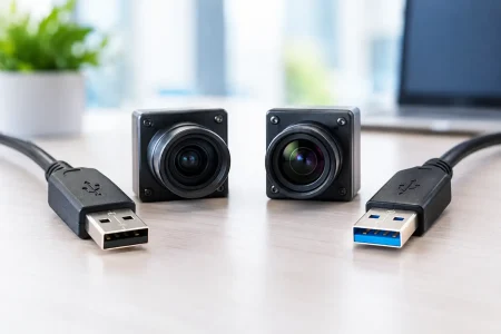
USB camera modules simplify integration with PCs, industrial computers, and platforms that already support UVC. USB 2.0 is practical for moderate-resolution video and lower data rates. USB 3.0 provides much more headroom for high-resolution, higher-frame-rate, or less-compressed streams. The trade-off is connector size, cable management, and host-side bandwidth sharing.
DVP remains useful in cost-sensitive or legacy embedded systems, but its parallel bus consumes more pins and becomes less attractive as resolution and frame rate rise. The correct interface depends on the host processor, cable length, mechanical architecture, expected data format, and future product roadmap. Confirm lane count, lane speed, clocking, connector availability, and ISP compatibility before committing to a module.
Design the PCB and Flex Path as High-Speed Signal Paths
Board-level camera integration is not a matter of connecting pins in a schematic. For MIPI CSI-2 and other high-speed interfaces, follow the module and processor layout guidance for controlled impedance, differential pair routing, spacing, return paths, and length matching. Avoid unnecessary vias, stubs, sharp corners, and layer transitions. Keep sensitive lanes away from switching regulators, RF antennas, high-current motor paths, and aggressive clock traces.
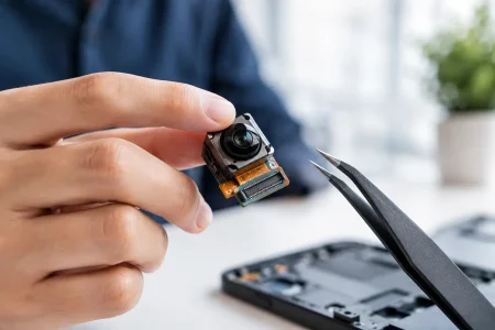
The flexible printed cable is part of the transmission channel, not merely a mechanical accessory. Its length, bend radius, shielding, grounding method, and connector retention all affect reliability. A short FPC may be ideal for a compact product, while a separate camera board with a shielded cable can be better for a system exposed to vibration, distance, or electrical noise.
Connector choice deserves early mechanical review. Verify insertion direction, mating cycles, retention force, assembly access, and whether the connector can tolerate the expected vibration and service conditions. For endoscope and other small-diameter applications, cable routing, strain relief, and heat transfer can be more limiting than the imaging electronics.
Build a Clean Power, Clock, and Reset Strategy
Image sensors are sensitive to supply noise. Separate analog, digital, and I/O rails as recommended by the sensor documentation, use appropriate local decoupling, and sequence rails correctly. A power design that appears stable on a basic multimeter can still introduce horizontal noise, frame instability, or intermittent startup failures.
Place switching regulators far enough from the sensor and analog supply path to reduce coupling. Where the design allows, low-noise regulators or filtered rails may be justified for the analog section. Validate supply ripple and startup behavior with an oscilloscope under real operating conditions, including LED activation, wireless transmission, motor movement, and peak processor load.
Clock quality matters as well. Use the specified frequency and jitter performance, and keep clock traces short and protected from noise. Reset, standby, and I2C control lines must be defined for normal startup, host reboot, firmware update, and unexpected power interruption. A camera that only starts correctly in a perfect lab sequence is not ready for commercial deployment.
Plan the ISP Pipeline and Software Control Early
A sensor image is not a finished image. Exposure control, gain, white balance, demosaicing, noise reduction, sharpening, lens shading correction, and color correction can be performed in a host ISP, sensor ISP, or external processor. The best arrangement depends on available host resources and how much image consistency the application requires.
For a product with controlled lighting and a fixed scene, locking selected image parameters can improve repeatability. For security or outdoor equipment, automatic exposure and wide dynamic range behavior may matter more. Ask for tuning support based on real scenes, not only laboratory charts. Test difficult conditions such as LED flicker, backlight, dark surfaces, specular metal, mixed color temperatures, and motion.
Make software ownership clear. The team should know who supplies drivers, device-tree settings, register configurations, image tuning files, and version control for production firmware. This is especially relevant when the host platform changes during development or when a product must remain in production for years.
Validate the Full Assembly Before Volume Production
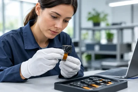
Module-level testing is necessary but insufficient. Validate the camera after it is installed in the final enclosure, with final cables, lens window, lighting, thermal conditions, and host software. Cover image quality, frame drops, startup reliability, electromagnetic compatibility, temperature performance, vibration, and connector durability.
Production validation should include a repeatable acceptance method. Depending on the application, this may measure focus position, dead pixels, color response, white balance, distortion, illumination uniformity, or calibration data. Define pass-fail limits that reflect application needs rather than idealized specifications. Overly strict cosmetic standards increase cost; loose standards create field failures.
For custom programs, engage a manufacturing partner while the mechanical envelope and host architecture are still flexible. SincereFirst can support this process with camera module selection, optical matching, interface definition, rapid custom samples, and scalable manufacturing controls backed by more than 30 years of imaging R&D experience.
The strongest camera integration is the one that remains predictable after thousands of units, varied lighting conditions, shipping vibration, software updates, and real operator use. Build that predictability into the first specification, and the final device will have intelligent eyes that earn trust in the field.