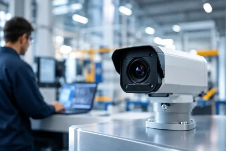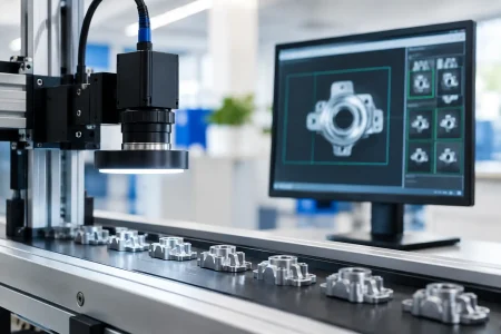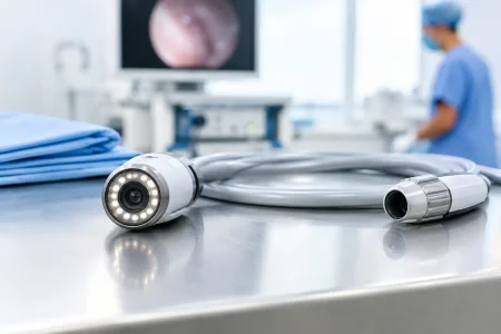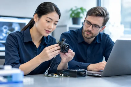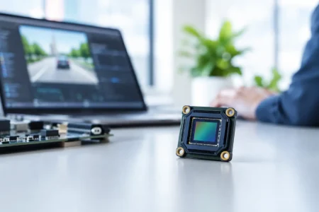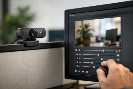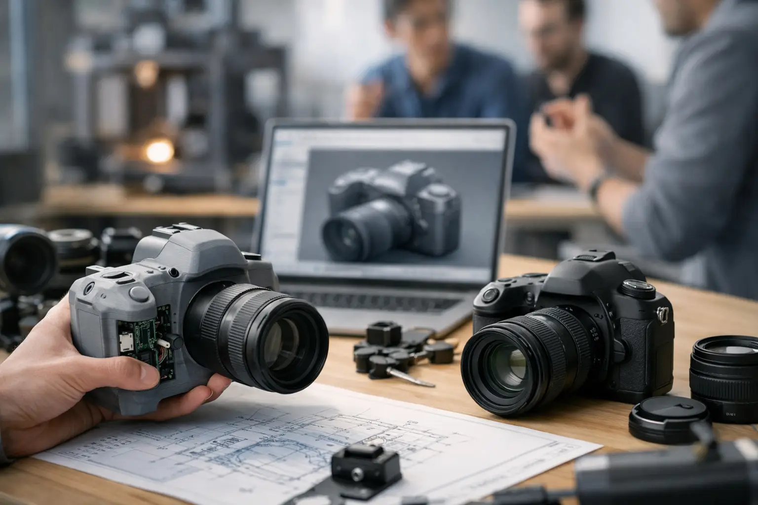
A camera prototype can look promising on a bench and still lose months to integration failures: an FPC that will not route cleanly, an autofocus lens that exceeds the enclosure height, unstable exposure under the actual LEDs, or a sensor that becomes unavailable just as the design is approved. Knowing how to shorten camera prototyping cycles means removing these late-stage surprises before tooling, certification, and purchasing commitments make changes expensive.
For OEMs developing robotics, medical devices, industrial equipment, smart security products, or compact consumer hardware, speed is not simply a matter of receiving samples quickly. The real objective is to reach a production-valid imaging architecture with fewer design spins. That requires a disciplined requirement definition, an intelligent module selection strategy, parallel electrical and optical validation, and a camera supplier that can translate prototype findings into manufacturable hardware.
Start With an Imaging Requirement, Not a Sensor Name
Many projects start with a request for a specific sensor model, resolution, or interface. Those are necessary inputs, but they do not define camera performance in the finished device. A 5MP MIPI camera module may be appropriate for a compact inspection tool, while a 2MP global-shutter module may produce better results on a moving robotic arm. The right choice depends on the scene, working distance, illumination, motion, and processing pipeline.
Before requesting samples, document the operating conditions that affect image quality. Define the field of view, target distance, minimum object size, lighting type, frame rate, acceptable blur, low-light behavior, and color requirements. Include mechanical limits such as module thickness, lens height, cable length, bend radius, connector location, and heat sources near the camera.
The interface also deserves early attention. MIPI CSI-2 is often the best fit for high-throughput embedded platforms, but it requires board-level signal integrity and processor support. USB UVC modules can reduce software integration effort for PCs and many Linux systems, yet module size, power budget, and cable length may be less favorable. DVP remains useful on selected legacy or cost-sensitive platforms. Choosing an interface only because it is familiar can create an avoidable redesign later.
Write a one-page camera brief
A concise camera brief keeps the project moving. It should state the intended application, image-quality targets, host processor, operating environment, mechanical envelope, estimated annual volume, and the validation deadline. It should also distinguish between requirements that are fixed and preferences that can change.
For example, a device may require a 90-degree horizontal field of view and a 15 mm module height, but 1080p versus 4MP may remain open until image testing. This gives engineering teams and suppliers room to optimize the solution instead of forcing an early compromise around an incomplete specification.
How to Shorten Camera Prototyping Cycles With Proven Building Blocks
A custom camera module should not mean creating every component from zero. The fastest programs begin with a proven module platform, then customize only the elements that materially affect fit, function, or product differentiation. This approach preserves known-good electrical and optical designs while focusing engineering time where it has value.
A standard MIPI, USB2.0, USB3.0, or UVC camera module can often be adapted through lens selection, FPC length and orientation, connector type, mounting geometry, filter configuration, or firmware tuning. In specialized designs, the sensor board and lens board can be separated to fit a narrow enclosure. Endoscope applications may require a very small diameter module, a side-view direction, integrated LEDs, or a cable structure designed for repeated movement.
The trade-off is straightforward. A fully customized solution can achieve tighter mechanical integration or a unique imaging result, but it introduces more validation variables and longer lead times. A semi-custom module usually reaches functional testing sooner and provides a lower-risk path to pilot production. Product managers should reserve full custom development for constraints that cannot be solved with an established platform.
It is also wise to select a second sensor option early. Supply continuity, lifecycle status, and image tuning differences must be evaluated, but a qualified alternate can prevent a component allocation from stopping an otherwise ready product. This is especially relevant for devices with multi-year production plans.
Validate Optics, Electronics, and Software at the Same Time
Serial testing is a common source of delay. If the mechanical team waits for final optics, the firmware team waits for the carrier board, and the image-quality review happens after enclosure tooling, every issue becomes a schedule event. Parallel validation creates faster feedback and makes root causes easier to isolate.
Start optical testing with realistic targets and lighting rather than a basic live preview. Test the far and near limits of the working range. Check corner sharpness, distortion, color consistency, flare, exposure transitions, rolling-shutter artifacts, and focus stability. For machine vision applications, evaluate whether the images support the actual algorithm, not only whether they look sharp to the human eye. A barcode reader, crop-sorting system, or defect-detection model may prioritize contrast, motion performance, and repeatability over visual color rendering.
At the same time, verify the electrical path. Confirm MIPI lane configuration, clocking, power sequencing, electromagnetic interference, and host-side driver behavior. For USB modules, measure current draw and behavior during repeated connection cycles. Verify that the processor can sustain the required resolution and frame rate while running the final application workload.
A sample that works in a supplier reference setup is a useful first checkpoint, not final proof. The production device may introduce different ground paths, heat, LEDs, shielding, cable routing, and software load. Early testing on the actual host platform exposes those differences while changes are still practical.
Use a disciplined test matrix
Teams move faster when every sample has a clear purpose. Label samples by sensor, lens, filter, firmware version, cable construction, and board revision. Test against the same scenes and record pass or fail criteria before reviewing results. Without version control, teams often repeat tests because they cannot reliably identify what changed between two apparently similar modules.
A short weekly technical review is usually more valuable than a long review at the end of a prototype phase. It keeps decisions close to evidence: retain the lens, adjust the field of view, change the IR-cut filter, modify exposure settings, or alter the FPC exit direction. Small, documented decisions prevent a large pile of unresolved issues.
Bring Manufacturing Engineering Into the Prototype Phase
A camera design can be technically correct and still be difficult to build repeatedly. That is why design for manufacturability should begin with the first viable prototype, not after performance approval. Lens alignment, adhesive curing, sensor cleanliness, FPC handling, connector retention, and module mounting all influence yield and consistency.
Ask the supplier to review tolerances around the lens barrel, sensor position, mounting points, and cable route. In compact modules, a fraction of a millimeter can affect focus, stress the FPC, or interfere with the device housing. In medical and industrial products, requirements for cleanliness, ingress protection, sterilization exposure, temperature range, or vibration can change material and assembly decisions significantly.
The manufacturing review should also define inspection points. A practical plan may include optical performance checks, cosmetic inspection, electrical testing, and functional verification on a representative host. The exact test coverage depends on risk, volume, and application criticality. A consumer accessory and a medical imaging subsystem should not carry the same qualification burden, but neither should rely only on a visual inspection.
SincereFirst supports this transition by combining standard camera module platforms with custom optical, FPC, connector, and mechanical development. For buyers, the useful measure is not sample speed alone. It is whether the supplier can provide engineering feedback that makes the next sample closer to a manufacturable release.
Set Decision Gates That Prevent Endless Iteration
Fast projects need controlled decisions, not constant changes. Establish gates for feasibility, image-quality approval, mechanical fit, host integration, pilot build, and production release. At each gate, identify which requirements are verified, which risks remain open, and who has authority to accept a trade-off.
Do not continue optimizing parameters with little commercial impact once the device meets its real use case. A slightly wider field of view or marginally better low-light image may not justify another tooling change, especially when it affects schedule, cost, or supply stability. On the other hand, an unresolved motion artifact in a high-speed inspection system should not be treated as a minor issue simply because the prototype looks acceptable under static conditions.
The most effective camera programs combine fast samples with fast decisions. Define the imaging problem precisely, adapt proven module designs, test in the real device environment, and involve manufacturing engineers while changes are still inexpensive. That discipline turns a prototype from a promising demo into a camera system that can be built, supplied, and trusted at scale.