A vision project usually fails long before the first image is captured. It fails when the camera is chosen as a part number instead of a system component. That is why an embedded machine vision camera guide matters for product teams building robotics, medical devices, smart equipment, and industrial systems. The right module is not just about resolution. It is about interface fit, optical constraints, ISP behavior, mechanical envelope, supply continuity, and how fast you can move from sample to production.
What an embedded machine vision camera guide should help you decide
In embedded products, the camera is tied directly to processing architecture, enclosure design, cable routing, thermal load, and manufacturing yield. A USB camera may speed up development, but MIPI can reduce latency, power, and size in production hardware. A higher megapixel sensor may look stronger on paper, but if your lens, lighting, and processor cannot support it, image quality and system cost both suffer.
That is the central decision framework: define the task first, then match the imaging path to the task. Inspection, code reading, edge detection, object recognition, measurement, and teleoperation all stress the camera in different ways. The best embedded machine vision camera guide starts from application requirements, not marketing specifications.
Start with the imaging task, not the sensor
Engineers often begin by comparing sensor families and resolutions. That is useful, but secondary. The first questions should be practical. What feature size must the system detect? At what working distance? Under what lighting? At what speed? In what physical space? What compute platform will process the image?
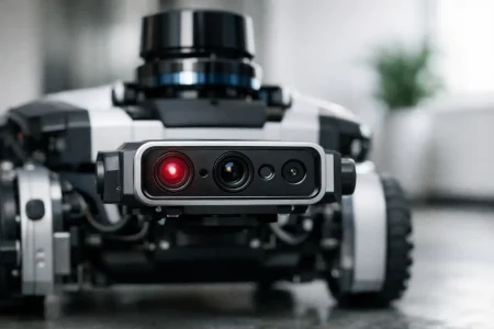
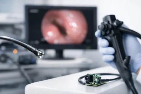
A warehouse robot avoiding obstacles has different requirements from a PCB inspection unit or a portable medical instrument. The robot may prioritize low latency, wide field of view, and stable performance under changing light. The inspection unit may need distortion control, repeatable color response, and very fine defect visibility. The medical device may place the highest value on compact dimensions, low heat, and signal stability in a tightly constrained housing.
Once those constraints are clear, the camera decision becomes narrower and more accurate.
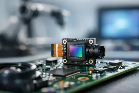
Sensor selection in an embedded machine vision camera guide
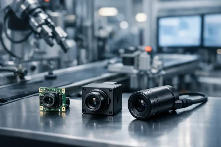
Sensor selection should balance pixel size, resolution, frame rate, dynamic range, sensitivity, shutter type, and long-term availability. No single sensor wins every project.
Global shutter sensors are often the safer choice for motion-sensitive machine vision. If the target or camera moves during exposure, rolling shutter distortion can affect recognition, measurement, and barcode reading. That said, rolling shutter sensors can still work very well in fixed-position systems with controlled lighting and slower object motion, often at a lower cost and with strong image quality.
Resolution should be driven by the smallest detail you need to inspect across the full field of view. Overspecifying resolution raises bandwidth, memory, processor load, and storage demands. In embedded systems, that can affect BOM cost and thermal design quickly. Higher resolution is only useful when the lens quality, focus tolerance, and illumination are strong enough to support it.
Dynamic range also deserves more attention than it usually gets. In industrial and outdoor environments, bright highlights and deep shadows can appear in the same frame. A sensor with better dynamic range can preserve usable detail and reduce the burden on downstream image processing.
Interface choice affects the whole product
The interface is not a connector decision. It is a system architecture decision.
MIPI CSI-2 for compact, high-performance integration
MIPI camera modules are a common fit for embedded vision products that need low latency, compact size, and direct integration with an application processor or SoC. They are especially useful in robotics, smart terminals, handheld devices, and edge AI hardware. The trade-off is development complexity. Driver support, tuning, and board-level integration need closer coordination.
USB for faster development and broader compatibility
USB camera modules are often the fastest path for evaluation, prototyping, and products that benefit from plug-and-play integration. UVC support can simplify deployment on common operating systems. USB also works well when the host processor lacks a native camera interface. The trade-off is usually larger module size, higher power draw, and less optimization for tight embedded mechanical designs.
DVP and other legacy or specialized paths
Some cost-sensitive or established embedded platforms still use DVP interfaces. In the right design, DVP remains practical, especially where bandwidth demands are modest and processor support is mature. But for newer, higher-performance vision systems, it can become a bottleneck.
Optics matter as much as electronics
Teams often spend weeks comparing sensors and only hours defining the lens. That is backwards. A poor optical path can waste an excellent sensor.
Field of view must match the task. Wider is not always better. A very wide lens can capture more scene context, but it also reduces target pixel density and may introduce distortion that complicates measurement or detection. A narrower lens improves detail on target, but can make alignment less forgiving.
Focus strategy also matters. Fixed-focus modules support scale and mechanical simplicity, but only when the working distance is stable and the tolerance stack is controlled. Autofocus may help in user-facing or variable-distance products, though it introduces additional firmware behavior and moving parts. For industrial vision, fixed focus is often preferred for consistency.
Lens mount stability, IR performance, chief ray angle compatibility, and dust control should also be considered early. In production hardware, small optical mismatches create large field failures.
Image signal processing can help or hurt
ISP tuning is one of the least visible and most decisive parts of embedded vision performance. Auto exposure, white balance, sharpening, noise reduction, gamma, and color correction all shape what the algorithm or user actually sees.
For machine vision, the best-looking image is not always the most usable image. Heavy noise reduction can erase fine edges. Aggressive sharpening can create false contrast. Automatic behaviors that drift between scenes can reduce consistency in inspection or recognition tasks.
This is where application-specific tuning matters. A camera for color-based sorting needs different tuning from one used for OCR, SLAM, or microscopy. If your supplier cannot align sensor output, optics, and ISP behavior to the real use case, development time expands fast.
Mechanical and environmental constraints decide production success
In embedded products, camera selection does not end with image quality. The module must fit the enclosure, survive the operating environment, and support repeatable assembly.
FPC camera modules are valuable when space is limited and board placement is constrained. Board camera modules may be easier to handle in development and fixed industrial designs. Connector choice, cable bend radius, shielding, and retention force all affect reliability. In vibration-prone equipment, an image issue may actually be a mechanical issue.
Temperature is another common blind spot. Sensors, processors, and illumination sources all generate heat. Elevated temperature affects noise, stability, focus position, and long-term lifespan. If the product will operate outdoors, near motors, or inside sealed housings, thermal testing should happen early, not after EVT.
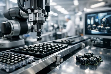
Production planning should influence camera choice from day one
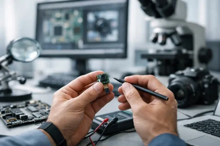
A module that works in ten prototypes is not automatically the right module for ten thousand units. Business buyers and design engineers both need to consider supplier stability, change control, test standards, and customization capability.
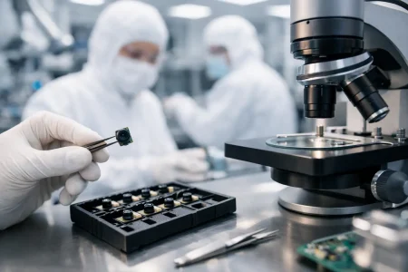
That includes sensor lifecycle risk, lens sourcing consistency, cleanroom assembly quality, and the ability to adjust cable length, connector orientation, board shape, glass stack, or housing fit. For OEM and ODM programs, speed matters too. Fast sample turnaround is useful only when it is backed by engineering support and scalable manufacturing discipline.
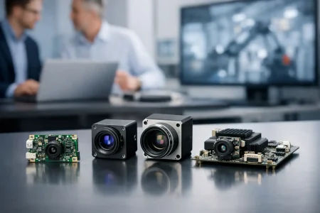
This is where a manufacturing-led partner can reduce project risk. Companies such as SincereFirst support standard and custom embedded camera development with module engineering, optical integration, and production capacity aligned to commercial device programs.
Common mistakes this embedded machine vision camera guide can help you avoid
One common mistake is specifying a camera before validating lighting. Another is selecting the highest resolution available and underestimating the processor, memory, and heat budget required to handle it. A third is treating interface support as a software detail instead of a schedule risk.
There is also a recurring procurement error: buying a sample based on performance and qualifying a supplier based on price alone. In embedded vision, supply consistency and engineering responsiveness often matter more than small unit-cost differences. A low-cost module that slips integration milestones or fails in field conditions becomes expensive very quickly.
How to narrow the right camera module faster
A practical evaluation flow is straightforward. Define the inspection or perception target. Map the required field of view and minimum detectable feature size. Choose shutter type and frame rate based on motion. Match the interface to the host platform. Confirm optics and working distance. Review ISP needs. Then test the module in the real mechanical and lighting environment.
If customization is likely, raise it early. Changes to lens holder height, board outline, cable type, connector position, and image tuning are much easier before the rest of the hardware stack is frozen. Early alignment between product, hardware, firmware, and sourcing teams saves months later.
The strongest embedded vision programs are rarely built around a single headline specification. They are built around fit – sensor fit, optical fit, interface fit, mechanical fit, and production fit. When those pieces align, the camera stops being a sourcing problem and becomes a reliable foundation for the product you are trying to ship. Choose with that standard in mind, and the path from prototype to volume gets much shorter.