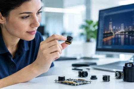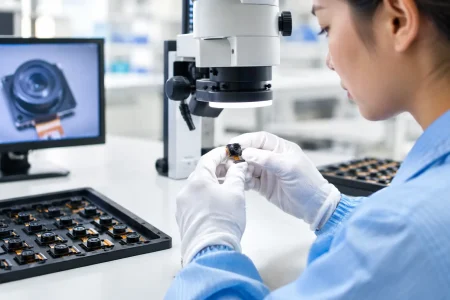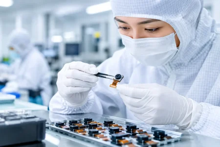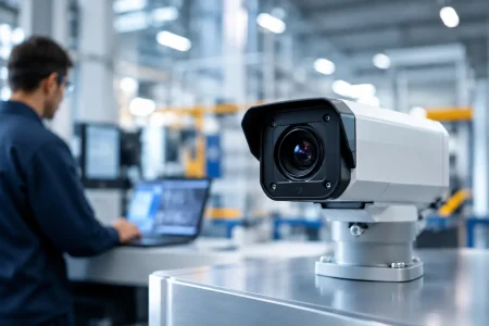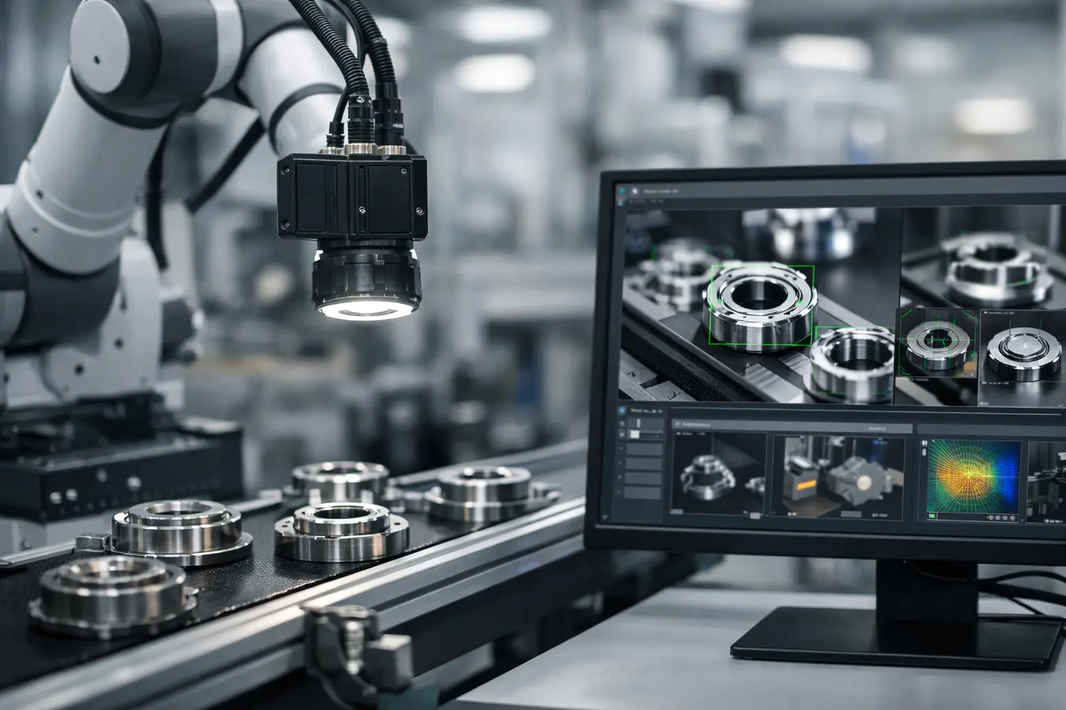
A camera that produces a sharp image on an engineer’s bench can still fail on a production line. Conveyor vibration, reflective parts, fluctuating ambient light, cable noise, and short cycle times all change the result. This industrial vision integration guide is designed for OEMs and system integrators who need to turn an imaging requirement into a dependable, manufacturable inspection system.
The central engineering question is not simply which camera has the highest resolution. It is whether the complete imaging chain can detect the required condition at production speed, under the real mechanical and environmental conditions of the machine. Camera selection matters, but sensor format, lens geometry, illumination, interface bandwidth, processing architecture, and validation discipline must work as one system.
Start With the Inspection Decision
Define what the machine must decide before selecting a module or sensor. A vision system may need to confirm presence, read a code, measure a dimension, identify orientation, classify a surface defect, or guide a robot to a pickup point. Each task has a different tolerance for blur, distortion, contrast variation, and processing delay.
A requirement such as “inspect small defects” is not sufficient for a supplier or design team. Specify the smallest defect size, its contrast against the part, the inspection area, working distance, target throughput, and acceptable false-pass and false-reject rates. Also identify whether parts arrive in a fixed position or require localization. These inputs determine the pixels required on the object, not just the resolution written on a camera data sheet.
For example, a 0.2 mm scratch cannot be reliably inspected merely because it occupies one pixel. In most applications, the feature needs several pixels across its critical dimension, plus enough optical contrast to separate it from normal surface variation. The required margin depends on the algorithm and consequence of an error. Measurement and safety-related applications generally demand more margin than simple presence detection.
Match Resolution to Field of View
Start with field of view, then calculate pixel density. If a 200 mm-wide part must reveal a 0.5 mm feature and the project requires five pixels across that feature, the image needs at least 2,000 pixels across the relevant axis. Add margin for part position variation, lens distortion correction, and any cropped inspection regions.
Higher resolution is not automatically better. More pixels increase data rate, memory use, processing time, lens demands, and sometimes cost. If the inspection task only requires a coarse pass/fail decision, a lower-resolution sensor with faster frame rate and strong lighting may deliver a better production result.
Build the Image Chain Around the Part
Industrial imaging performance is created before software receives a frame. The sensor captures the available optical signal; the lens maps that signal to the image plane; illumination makes relevant features visible; and mechanical design holds everything in place. A weak decision in any one area can limit the entire system.
Select the Sensor for Motion and Dynamic Range
Global shutter sensors are usually the safer choice when parts move quickly, a robot carries the camera, or strobe illumination is used. They expose all pixels at the same moment, preventing the skew and shape distortion associated with rolling shutter capture. Rolling shutter sensors can be appropriate for stationary scenes, lower-cost equipment, or applications where exposure timing is controlled, but the motion trade-off should be verified with real samples.
Sensor size, pixel pitch, sensitivity, and dynamic range should be considered together. Larger pixels can improve low-light response, while high dynamic range can help with mixed bright and dark features. However, a broad dynamic range is not a substitute for controlled lighting. If glare hides a defect, capturing more tonal range may still leave the defect indistinguishable from reflections.
Color imaging is valuable when color itself is the inspection variable, such as cap color, label verification, produce grading, or wire identification. Monochrome imaging often provides higher effective detail and sensitivity for edge measurement, code reading, and contrast-based defect inspection. Near-infrared sensitivity or a specialized filter may be needed for materials that are difficult to separate under visible light.
Treat Optics and Lighting as Engineering Components
Lens selection should account for working distance, field of view, required resolution, depth of field, allowable distortion, and installation space. A compact lens may fit the enclosure but deliver inadequate edge sharpness or unacceptable distortion at the required measurement tolerance. For dimensional inspection, telecentric optics may be justified because they reduce perspective error and maintain magnification across a limited depth range. They cost more and take more space, so they are best reserved for applications where measurement accuracy supports the investment.
Lighting should reveal the feature while suppressing everything that creates false contrast. Backlighting is effective for silhouettes, gaps, and dimensional profiles. Low-angle lighting can expose scratches and raised texture. Diffuse dome lighting helps control glare on curved or reflective surfaces. Coaxial lighting is often useful for flat, reflective parts. The right choice depends on material finish, feature direction, part geometry, and whether the target must be inspected from one or several angles.
Do not test lighting with a single ideal sample. Evaluate acceptable parts, known bad parts, surface variants, and parts from different production batches. A lighting arrangement that looks excellent on one polished component may become unstable when oil, dust, or normal finishing variation enters the process.
Choose an Interface and Compute Architecture Early
The camera interface affects enclosure design, cable routing, processor selection, software complexity, and future serviceability. It should be selected at the same time as frame rate and image size, not after the optical design is complete.
MIPI CSI-2 camera modules are well suited to compact embedded equipment where the processor board is close to the camera and direct integration with an application processor is required. They support high data throughput with low hardware overhead, but cable distance and board-level signal integrity require careful control. MIPI is common in robotics, handheld instruments, smart terminals, and embedded industrial devices where space is limited.
USB camera modules offer a practical path for systems using industrial PCs, edge computers, or standard operating systems. UVC compatibility can simplify deployment because the camera follows a widely supported video class standard. USB 3.0 provides substantially more bandwidth than USB 2.0 for high-resolution or higher-frame-rate imaging. The trade-off is that cable length, connector retention, host-controller capacity, and shared bus traffic must be planned.
The usable data rate is more important than the interface label. Calculate frame size, pixel format, frame rate, protocol overhead, and the number of cameras on each bus. Raw image formats preserve more information for inspection algorithms but require more bandwidth and compute resources. Compressed video reduces transmission demands but can introduce artifacts that are unacceptable for metrology or fine defect detection.
Processing location also matters. A camera feeding an edge processor can support flexible algorithms, AI models, data logging, and remote updates. A dedicated vision controller may be preferable where deterministic response, simplified qualification, and long-term configuration control have higher value. The best architecture depends on cycle time, software ownership, cybersecurity requirements, and the expected service life of the equipment.
Industrial Vision Integration Guide: Design for the Factory
A production camera system must survive more than the first demonstration. Mounting stiffness, focus retention, connector strain relief, heat dissipation, ingress protection, and electromagnetic compatibility affect image quality and uptime directly. If the camera mount shifts by a fraction of a millimeter after repeated machine cycles, a calibrated measurement can drift even when the sensor is operating correctly.
Use locking connectors where vibration is expected, secure cable paths away from moving mechanisms, and allow adequate bend radius at the module connection. Confirm that the enclosure window does not introduce reflections, contamination, or optical distortion. If a protective window is required, define its material, coating, spacing, and cleaning method as part of the optical stack.
Temperature deserves specific attention. Sensor noise, lens focus, illumination output, and processor performance can change as an enclosure heats up. Test after thermal soak rather than only at room temperature. For outdoor or partially exposed equipment, test the effect of sunlight, dust, condensation, and changing ambient light on the inspection result.
Validate the System With Production Evidence
A disciplined integration process reduces expensive late-stage changes. The work should progress from feasibility images to a controlled pilot and then to production qualification:
- Capture representative images of good and defective parts using candidate lighting, optics, and sensor settings.
- Confirm that the system meets pixel density, focus, contrast, exposure, and throughput requirements at the intended working distance.
- Run a pilot with real motion, machine vibration, operator interaction, and expected production variation.
- Establish acceptance criteria, calibration procedures, image retention rules, and a method for monitoring false results after deployment.
The pilot phase often exposes requirements that were absent from the original specification. Parts may rotate more than expected, contamination may accumulate on a protective window, or a line-speed change may reduce exposure time below the usable limit. Finding these conditions before release is far less costly than correcting them after installation.
For high-volume OEM products, validation must also include manufacturing repeatability. A design that works with one hand-adjusted camera is not ready for scaled production. Define mechanical datums, lens focus control, module test criteria, firmware versions, and incoming inspection standards. If multiple cameras are used, specify whether color response, exposure behavior, and focal position must be matched unit to unit.
Select a Camera Partner That Can Support Change
Industrial programs rarely remain fixed. A processor may change, the enclosure may shrink, a customer may request a different field of view, or a supply constraint may require a qualified sensor alternative. This is where camera-module customization capability becomes commercially important.
Assess a supplier’s ability to support sensor selection, lens integration, FPC or board-to-board connection design, USB or MIPI interface requirements, optical tuning, sample delivery, and production testing. Ask how configuration changes are documented and how component lifecycle risks are managed. A low unit price has limited value if a revised cable, lens holder, or firmware setting creates a long requalification cycle.
SincereFirst supports OEM and industrial vision programs with standard and customized camera modules, optical components, and manufacturing capability built for prototype-to-volume transitions. The practical advantage is not a catalog alone. It is access to engineering decisions that keep the camera, optics, interface, and mechanical package aligned as the product moves toward production.
A well-integrated vision system earns confidence one inspection at a time. Build the requirement around the decision the machine must make, test it against real variation, and leave enough design margin for the conditions the factory will eventually introduce.