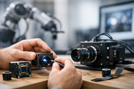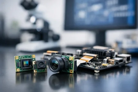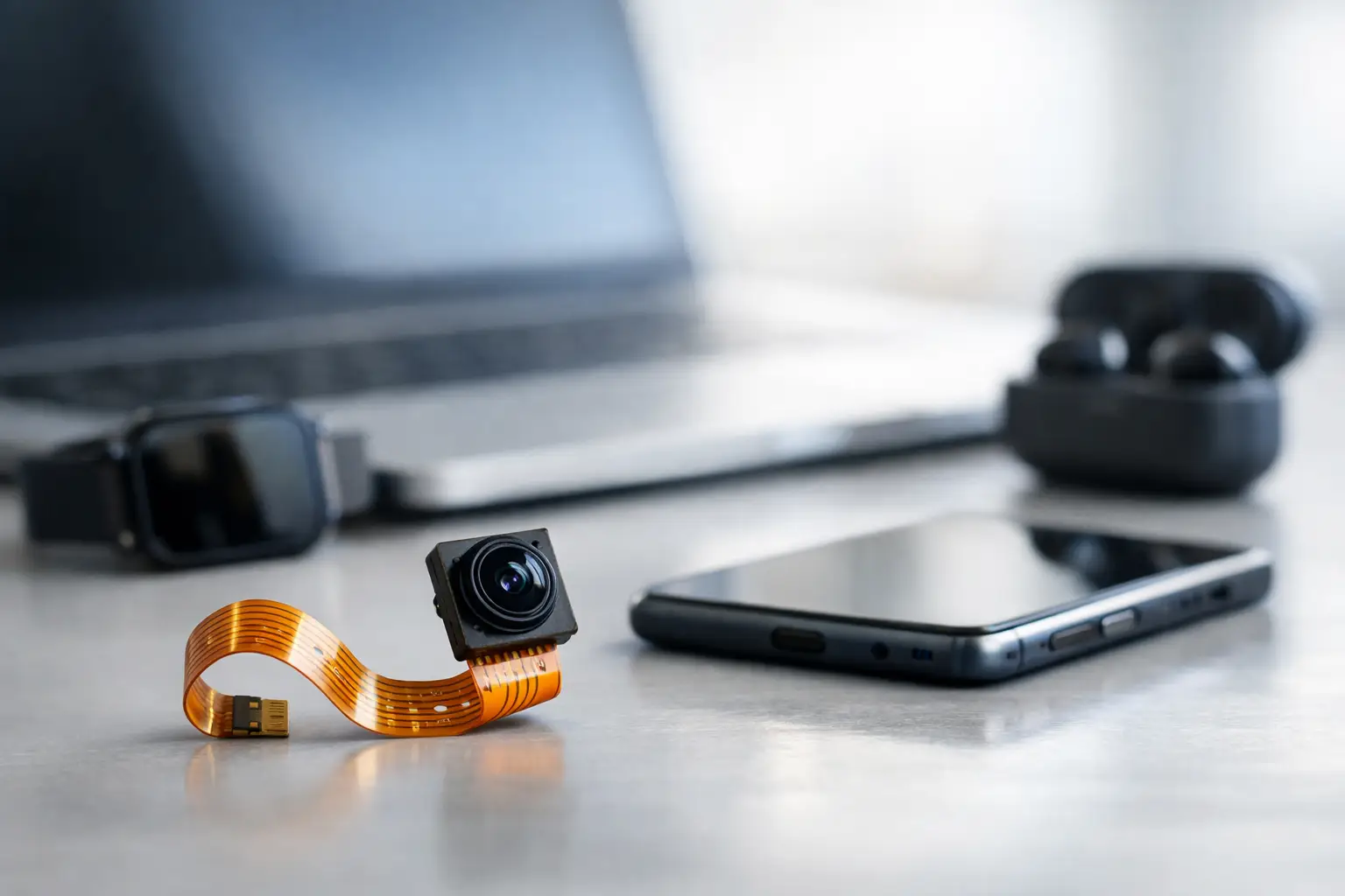
A camera can meet every image-quality target on the bench and still fail the product design because the cable cannot bend where the enclosure requires it. That is the practical answer to why use fpc camera module assemblies in embedded products: the camera, interconnect, and mechanical layout must work as one system. For compact devices, a flexible printed circuit (FPC) camera module often provides the routing freedom that a rigid board-and-cable arrangement cannot.
For OEMs, system integrators, and engineering teams, the decision is not simply about choosing a smaller camera. It is about controlling package thickness, installation geometry, signal integrity, assembly repeatability, and supplier scalability before the design reaches production.
Why Use FPC Camera Modules for Embedded Vision?
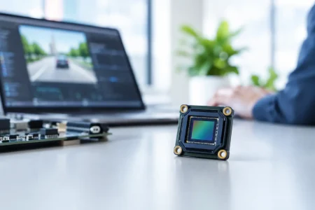
An FPC camera module combines an image sensor, lens assembly, and flexible printed circuit. The flexible tail carries power, control, clock, and image data signals to the host board through a connector, commonly for MIPI CSI-2 or DVP-based designs. Unlike a rigid PCB module that must be mounted near the processor board, an FPC design allows the camera head to sit where the optical path needs to be while the tail follows the available internal route.
This matters in products with thin housings, curved surfaces, moving sections, or crowded mechanical stacks. A robot gripper may need a camera at the end effector while the processing board sits deeper in the arm. A medical handheld may require the lens at the device tip but have limited clearance behind it. A smart access terminal may need the sensor positioned at an exact face-height angle without redesigning the main board.
The FPC is not only a cable substitute. It is part of the module architecture. Its length, bend area, trace design, shielding requirements, connector orientation, and stiffener placement should be specified around the device rather than treated as an afterthought.
Space Savings Come From Placement Freedom
The strongest reason to select an FPC camera module is mechanical flexibility. The module head can be separated from the host PCB, allowing engineers to use otherwise inaccessible space inside the enclosure. This can reduce the depth of the optical stack, improve lens alignment with an opening or cover window, and make room for batteries, antennas, heat sinks, or other high-priority components.
FPC tails can be folded and routed around internal features within defined bend limits. That gives industrial designers greater freedom, but it does not remove engineering constraints. Very sharp bends, repeated flexing, or routing near heat sources can reduce long-term reliability. If the module will move during normal operation, such as in a hinged product or articulated mechanism, the flex cycle requirement must be identified early.
A rigid module may still be the better option when the camera is mounted directly beside the processor, the enclosure has ample space, and lowest component cost is the main priority. FPC modules add value when the product layout benefits from separation between the camera head and the system board.
Better Optical Positioning
The best location for the sensor is determined by the field of view, working distance, lens height, cover-glass thickness, illumination angle, and obstruction risk. It is rarely determined by where the main PCB happens to fit.
With an FPC camera module, the lens can be placed close to the external aperture while the processor board remains in a protected or serviceable location. This helps reduce tunnel effects caused by a deep camera recess and can simplify alignment with illumination components. For barcode reading, machine inspection, facial imaging, and telepresence devices, that placement control can directly affect usable image quality.
Routing and Interface Design Need Equal Attention
Many embedded cameras use MIPI CSI-2 because it supports high data rates with low pin count, making it a practical interface for compact products. FPC camera modules are also available with DVP, USB, and other interfaces depending on the host platform and application requirements.
Interface selection should start with the processor and software environment, not with the camera module alone. Engineers need to verify lane count, supported sensor drivers, maximum data rate, connector type, power rails, clocking, and image signal processor compatibility. A high-resolution sensor is of little value if the host cannot receive, process, or store its output at the intended frame rate.
FPC length is especially relevant for high-speed image signals. A longer tail may help packaging, but it can increase signal-loss and electromagnetic-interference risk. Controlled impedance, differential-pair routing, grounding strategy, and connector quality all influence performance. For demanding designs, the module supplier should evaluate the complete interconnect path rather than providing a generic cable length without system context.
Customization Makes FPC Modules More Valuable
Standard camera modules are useful for quick proof-of-concept work, but production devices commonly require adjustments. The lens may need a specific field of view or focus distance. The FPC may need a different length, exit direction, pin definition, or connector. The module outline may need to clear a bracket, sealing feature, or display assembly.
This is where a custom FPC camera module can reduce redesign risk. A qualified manufacturer can align the sensor, lens, FPC layout, connector, and mechanical dimensions with the final device architecture. Useful customization points often include sensor model, resolution, lens type, fixed-focus distance, infrared filter configuration, FPC length, connector selection, module thickness, and mounting features.
Customization should be disciplined, not open-ended. Changing a lens affects image circle, distortion, depth of field, and low-light performance. Changing an FPC can affect electrical behavior and assembly handling. The most efficient programs lock key requirements early: scene distance, field of view, resolution, frame rate, interface, operating environment, target module size, and expected annual volume.
Manufacturing Consistency Is Part of Image Quality
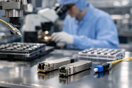
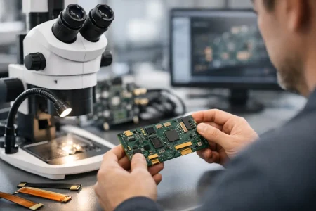
A camera module is an electro-optical assembly, so image performance depends on more than the sensor specification. Lens centering, focus accuracy, adhesive control, dust management, sensor alignment, and final inspection all affect field performance. In commercial deployments, variation between units can create more problems than a modest difference in headline resolution.
For this reason, procurement teams should assess how the supplier controls production. Questions should cover cleanroom assembly, incoming-material inspection, optical testing, focus verification, traceability, aging procedures, and capacity planning. A sample that performs well is only the first gate. The supplier must be able to reproduce the same optical and electrical result across pilot builds and volume orders.
SincereFirst supports this process with standard and custom embedded camera module development, combining optical selection, FPC design, module assembly, and scalable manufacturing for application-specific imaging requirements.
Where FPC Camera Modules Fit Best
FPC camera modules are particularly effective where product geometry drives the design. In robotics, they allow vision heads to be placed near grippers, inspection points, or navigation surfaces. In medical and dental equipment, they support compact imaging heads and controlled optical placement. In security terminals and smart-city equipment, they help position cameras behind protective windows while keeping processing electronics protected inside the housing.
They are also widely suited to industrial automation, agricultural equipment, smart appliances, handheld instruments, kiosks, and compact consumer electronics. However, a harsh environment may require more than a flexible module alone. Vibration, moisture, temperature cycling, chemical exposure, and electromagnetic noise can call for reinforced mounting, sealing, shielding, conformal protection, or an alternative module structure.
How to Specify an FPC Camera Module Correctly
A productive supplier discussion begins with the application rather than a request for a generic megapixel count. Define what the camera must see, at what distance, under which lighting conditions, and with what processing platform. Then provide the available module envelope, lens opening position, FPC routing path, connector details, and environmental limits.
Before design freeze, confirm focus performance on the actual target, not only a test chart. Check color behavior under the intended illumination, low-light noise, motion artifacts, latency, and image quality through the complete host system. For MIPI designs, validate the sensor driver and board layout early. For production, agree on acceptance criteria that address both electrical operation and optical output.
The right FPC camera module gives a product team more than a compact imaging component. It gives the mechanical and electrical design room to put intelligent vision where it creates the most value – while preserving a practical path from prototype to stable volume production.