A traffic camera can be mechanically installed in an afternoon and still fail its real job after sunset. In this smart traffic camera module case study, a smart-city equipment OEM needed a compact imaging design that could retain useful vehicle detail across glare, vibration, heat, and changing light without creating a difficult-to-manufacture enclosure.
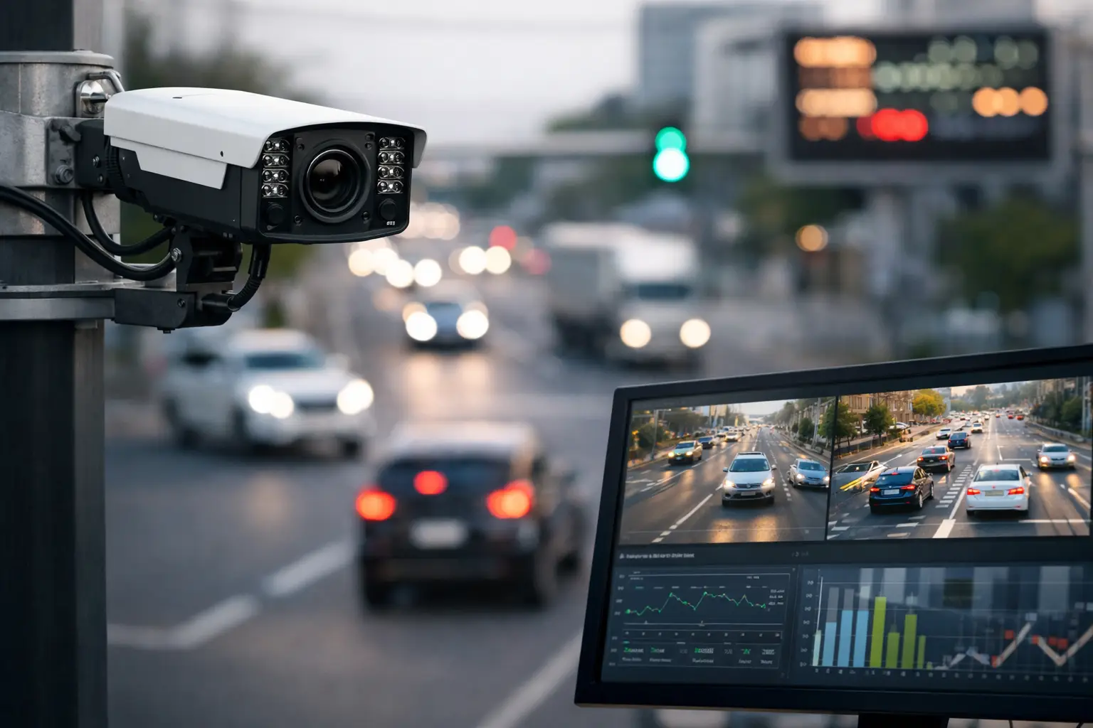
The customer was developing a networked roadside unit for intersection monitoring and traffic-flow analytics. Its earlier prototype used a consumer-oriented camera board that produced acceptable daytime video but showed motion blur, clipped headlights, and unstable image quality in high-contrast scenes. The module also required too much depth behind the front window, forcing compromises in the enclosure design.
This is a representative engineering case. Customer-identifying details have been withheld, while the design decisions and validation approach reflect the issues that camera-module buyers commonly face in traffic infrastructure projects.
Smart Traffic Camera Module Case Study: Project Conditions
The application did not require a camera module in isolation. It required an imaging subsystem that could support an edge processor, a protective housing, an IR-cut filter strategy, thermal management, and a production plan. The customer’s primary requirement was dependable video for vehicle detection, lane occupancy, and incident review at a fixed intersection.
Daytime resolution was not the main constraint. The difficult scenes occurred at dawn, dusk, and night, when dark vehicle bodies, reflective license plates, LED headlights, streetlights, and wet pavement appeared in the same frame. The team also needed a field of view wide enough to cover multiple lanes while preserving sufficient pixel density in the priority detection zones.
The first design review established three operating realities. First, a wide-angle lens could cover the intersection but would introduce distortion that the analytics pipeline had to correct. Second, a higher-resolution sensor could improve crop detail but would raise bandwidth, processing, storage, and thermal demands. Third, exposure settings suitable for slow-moving traffic would not necessarily control blur on vehicles passing through the near lanes.
Rather than select a module solely from a resolution table, the project team defined an image-quality target around the actual scene: usable detection performance under headlight glare, controlled highlights, readable vehicle contours, and consistent color during the day.
Selecting the Sensor, Lens, and Interface Together
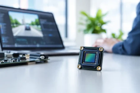
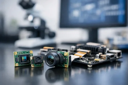
The engineering team evaluated a CMOS image sensor with high dynamic range capability, paired with a low-distortion automotive-style lens configuration. The selected reference design used a compact MIPI camera module for direct connection to the embedded vision processor. MIPI CSI-2 was appropriate because the processor board was inside the same roadside unit and required high throughput with low latency.
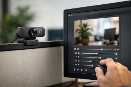
A USB camera module would have simplified early bench testing and can be a good choice for external or PC-based systems. For this design, however, USB added connector volume and did not offer the same board-level integration path. A DVP interface was also considered, but the required image data rate and processor architecture made MIPI the more practical option.
The lens decision mattered as much as the sensor decision. A very wide lens would have reduced the number of camera units per intersection, but extreme edge distortion created less reliable vehicle geometry near the frame boundaries. The final optical direction favored a moderately wide field of view with calibrated distortion correction. This increased the number of placement considerations, yet it delivered more consistent analytics coverage where lanes and stop lines mattered most.
Lens aperture was tuned for low-light collection, but opening the aperture too far would reduce depth of field and make assembly tolerances more sensitive. Roadside applications often have fixed scene distances, which helps. Still, the focus range needed to account for near-lane vehicles, farther lanes, and the mounting variation that occurs in volume production.
The Low-Light Problem Was Not Solved by Sensor Sensitivity Alone
The original prototype increased gain aggressively at night. That made dark areas brighter, but it also amplified noise and weakened the contrast needed by detection software. The revised design used a more balanced image-tuning strategy: exposure control, gain limits, high dynamic range behavior, noise reduction, lens transmission, and processor-side image signal processing were evaluated as one system.
Headlight glare required particular attention. When the system met a bright headlight against a dark background, automatic exposure could pull the entire scene down or allow the highlight to bloom across adjacent pixels. The team tested several scenes with approaching vehicles, cross traffic, reflective signs, and wet pavement. A high dynamic range sensor mode improved highlight control, but its effectiveness depended on motion and scene conditions. Multi-exposure HDR can introduce artifacts when objects move quickly, so it was validated against the target vehicle speeds rather than assumed to be universally better.
For night operation, the housing design retained provision for supplemental illumination where site conditions required it. This was not treated as a substitute for sound imaging design. Added illumination affects power consumption, heat, glare, and local compliance requirements. In many city deployments, available street lighting may be sufficient for traffic analytics, while plate-focused capture or poorly lit approaches may require a separate illumination strategy.
Mechanical Integration Became an Image-Quality Requirement
The camera module had to fit behind an optically clear front window within a weather-protected enclosure. That front window introduced a practical risk often missed in early demonstrations: reflections between the lens, cover glass, and internal surfaces can become visible at night. Small changes in lens position, coating selection, hood geometry, or internal surface finish can materially affect the final image.
The project therefore moved from open-board testing to an enclosure-level optical test earlier than planned. The team checked for flare from nearby streetlights, reflections from status LEDs, and image degradation caused by condensation or contamination on the window. A camera module that performs well on a laboratory chart can produce a disappointing roadside image if the optical path is treated as an afterthought.
Thermal behavior also influenced the design. Sensor noise, lens focus stability, and electronics reliability can shift as enclosure temperature rises. The module layout had to keep heat-producing processors and power components from concentrating directly around the image sensor. Thermal pads, board spacing, and airflow paths were reviewed alongside the image requirements.
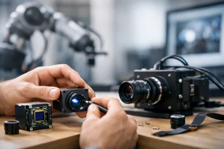
Vibration was another consideration. Intersection cabinets and poles can experience wind-induced movement, vehicle vibration, and repeated thermal cycling. The module connection, lens retention method, and mounting points needed to maintain alignment over the intended service life. This is where a production-oriented module supplier adds value beyond supplying a sensor and lens assembly.
From Sample Validation to Volume Production
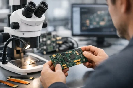
The customer’s engineering goal was a fast prototype cycle without creating a design that would be difficult to reproduce. SincereFirst supported this approach by aligning module customization with manufacturing controls from the beginning, including optical alignment, connector selection, flex routing, and test criteria.
The project used four development gates:
- Optical verification checked field of view, distortion, focus range, glare behavior, and image uniformity in representative lighting.
- Electrical verification confirmed MIPI lane configuration, frame rate, power sequencing, electromagnetic compatibility considerations, and processor compatibility.
- Environmental verification assessed temperature behavior, vibration tolerance, and the effects of the final front-window assembly.
- Production verification defined incoming inspection, image tests, traceability expectations, and acceptable cosmetic and optical limits.
The production gate was especially valuable. A lab sample can be hand-adjusted by an experienced engineer; a commercial camera module must meet the same optical and electrical standard across repeated builds. The team documented focus tolerances, lens alignment checks, sensor appearance criteria, and functional image testing before committing to larger quantities.
The resulting module direction reduced package depth versus the original board-level design, improved highlight control in the target night scenes, and gave the processor a direct high-speed image path. More importantly, it provided a defined basis for repeatable manufacturing rather than a prototype tuned around one favorable test condition.
What Buyers Should Specify Before Requesting a Quote
A traffic camera request that says only “1080p camera module” leaves too many variables unresolved. Buyers should provide the processor platform, preferred interface, target frame rate, field of view, mounting distance, expected illumination, operating temperature, enclosure constraints, and whether the system performs viewing, detection, recognition, or evidence capture.
The distinction between those use cases changes the module recommendation. Traffic-flow counting can tolerate different detail than license plate capture. A camera intended for broad situational awareness may prioritize wide coverage and dynamic range, while an analytics camera may prioritize controlled distortion, temporal consistency, and processor-compatible output. One module rarely optimizes every requirement at once.
A practical supplier discussion should also include anticipated annual volume and prototype timing. Low-volume samples may use a close standard configuration to accelerate testing. Once optics, interface, and mechanics are proven, a custom FPC shape, connector orientation, lens stack, or image tuning profile can be evaluated for the production version.
The strongest traffic imaging programs start by defining the scene that must be captured, not the resolution that looks best on a product sheet. When the sensor, optics, enclosure, processor, and factory test plan are engineered together, the camera module becomes a dependable part of the traffic system rather than the reason a field deployment has to be redesigned.