A 1.0 mm endoscope does not have much room for error. A slight fiber bend, an LED positioned a fraction too close to the lens, or an aggressive noise-reduction setting can turn a usable image into one with glare, haze, lost edge detail, or inaccurate color. For device engineers, learning how to optimize endoscope image clarity is not a matter of selecting the highest-resolution sensor. It is a system-level engineering task that starts with the clinical or industrial scene and ends with repeatable production validation.
Image clarity must also be defined correctly. In an endoscope, it combines resolution, contrast, color fidelity, even illumination, depth of field, noise control, and resistance to contamination. The right balance depends on whether the module must inspect a weld cavity, navigate a narrow industrial channel, or support medical visualization. Optimizing one parameter in isolation often weakens another.
How to Optimize Endoscope Image Clarity at the Optical Level
The optical train establishes the ceiling for image performance. No ISP setting can recover detail that never reaches the sensor, so lens selection, lens alignment, working distance, and field of view should be specified before image tuning begins.
Match field of view to the inspection task
A wider field of view helps an operator orient the probe in confined spaces, but it spreads the available pixels across more of the scene. Fine defects then occupy fewer pixels and may be harder to identify. A narrower field preserves more target detail, although it can make navigation and targeting more difficult.
Start with the smallest defect, feature, or anatomical structure that must be recognized at the intended working distance. Then calculate the required pixels across that feature rather than selecting resolution from a catalog alone. This approach gives optical, sensor, and mechanical teams a common acceptance target.
Control focus and depth of field
Many compact endoscopes use a fixed-focus lens because mechanical focusing is impractical at small diameters. The lens should therefore be optimized for the actual operating distance, not simply for a broad nominal range. If the object is usually 5 mm from the tip, a module focused around a much longer distance will look soft where it matters most.
A smaller aperture can increase depth of field, but it reduces the light reaching the sensor. This may require more LED output or longer exposure, both of which can introduce heat, glare, or motion blur. The correct answer depends on scene motion, allowable tip temperature, and available illumination power.
Protect contrast inside the module
Stray light is a frequent cause of washed-out endoscope images. Internal reflections from lens barrels, cover windows, adhesive, and polished metal surfaces lower contrast before the image reaches the sensor. Blackened internal surfaces, appropriate baffles, controlled adhesive placement, and low-reflectance mechanical finishes can make a measurable difference.
The distal window also deserves close attention. Its material, coating, thickness, and spacing from the lens influence reflections and image sharpness. In applications exposed to oils, moisture, or biological debris, the window must be selected for cleanability and chemical compatibility as well as optical transmission.
Build Illumination Around the Scene, Not Maximum Brightness
High brightness is not the same as useful illumination. Endoscopic scenes commonly include reflective surfaces, wet surfaces, dark recesses, and changing working distances. If illumination is too concentrated or too close to the optical axis, specular highlights can clip important image detail.
LED count, placement, viewing angle, diffuser design, drive current, and color temperature must work as a set. Ring illumination is often effective for forward-view modules, but LED spacing and geometry need to be matched to the lens field. Side-view endoscopes require a different approach because the illumination pattern must cover the viewing direction without creating a bright near-field hotspot.
Use a controlled target to evaluate uniformity from center to edge at the intended working distances. Also test shiny and dark samples that represent actual use conditions. A design that appears evenly lit on a matte white target may fail on chrome, damp tissue, or a lubricated metal bore.
Thermal design is part of illumination design. Increasing LED current can improve short-term brightness, but excessive heat may shift color, shorten LED life, affect adhesive stability, and create unacceptable tip temperatures. Pulse operation, thermal paths, current limits, and duty cycle should be qualified under worst-case operating conditions.
Select the Sensor and Interface for Real Image Conditions
Sensor resolution matters, but pixel size, sensitivity, dynamic range, shutter type, and signal output often matter more in compact endoscope integration. A very high-resolution sensor with small pixels can underperform in a low-light cavity if it produces excessive noise or requires exposure times that blur motion.
For moving probes or moving targets, a global shutter may be worth the trade-off in sensitivity or cost because it avoids geometric distortion. For static inspection with controlled lighting, a rolling shutter sensor can be a practical choice. The system decision should consider the entire capture chain, including frame rate, cable length, host processing capability, and power budget.
MIPI CSI-2 is well suited to compact embedded devices where bandwidth and board space are limited. USB and UVC interfaces simplify integration for many PC-based inspection systems and prototypes. Neither is universally better. The interface must reliably carry the selected resolution and frame rate while maintaining signal integrity through the planned cable and connector architecture.
Color performance should be evaluated under the module’s actual LED spectrum. White balance that looks acceptable under office lighting can be inaccurate under a cool or high-CRI LED source at the distal tip. For medical and material-identification applications, use known color targets and define tolerances that reflect the product’s use case.
Tune the ISP Without Erasing Useful Detail
Image signal processing can significantly improve perceived clarity, particularly where space limits sensor size and lighting power. It can also conceal defects, amplify artifacts, or produce inconsistent output between scenes. Treat ISP tuning as controlled image engineering, not a last-minute cosmetic adjustment.
Noise reduction should be strong enough to stabilize dark areas but restrained enough to preserve fine texture, edges, and defect boundaries. Overprocessing commonly creates a smooth, plastic appearance that looks clean on a display but removes the evidence an inspector needs. Similarly, aggressive sharpening can create halos around high-contrast edges and make noise appear as false detail.
Exposure control needs special care in scenes with bright reflections and deep shadows. Auto exposure that chases a small highlight can darken the rest of the image. Consider highlight protection, weighted metering, exposure limits, and application-specific auto-exposure behavior. In some industrial systems, fixed exposure and fixed illumination provide more repeatable results than automatic control.
Use lens shading correction to address natural brightness falloff, and correct defective pixels before sharpening. White balance, gamma, saturation, and contrast should be tuned against defined reference scenes. Save version-controlled ISP parameters with the module configuration so that samples, pilot builds, and production units do not drift apart.
Mechanical Assembly Can Make or Break Image Clarity
At endoscope scale, tiny mechanical deviations affect centering, focus, and image geometry. Lens tilt may produce sharpness on one side of the frame and softness on the other. Sensor placement error can shift the best-focus distance. Cable routing can introduce stress that changes alignment after assembly or thermal cycling.
Manufacturing controls should include active or validated passive alignment methods, adhesive cure profiles, optical-axis inspection, and defined handling procedures for the distal assembly. Cleanroom discipline is especially important because dust or adhesive contamination behind the cover window becomes a permanent image artifact.
For reusable devices, image quality must remain stable after the required cleaning, disinfection, or sterilization cycles. For disposable modules, the focus may be on cost-efficient, high-volume consistency. In both cases, the design should account for vibration, bend radius, tensile loading, ingress protection, and connector reliability. A sharp image at first power-on is not enough.
SincereFull endoscope camera modules can be configured across compact diameters and viewing formats, but the highest value comes from aligning the optical stack, illumination, interface, and assembly process to the device requirement early in development.
Validate Endoscope Image Clarity With Production-Relevant Tests
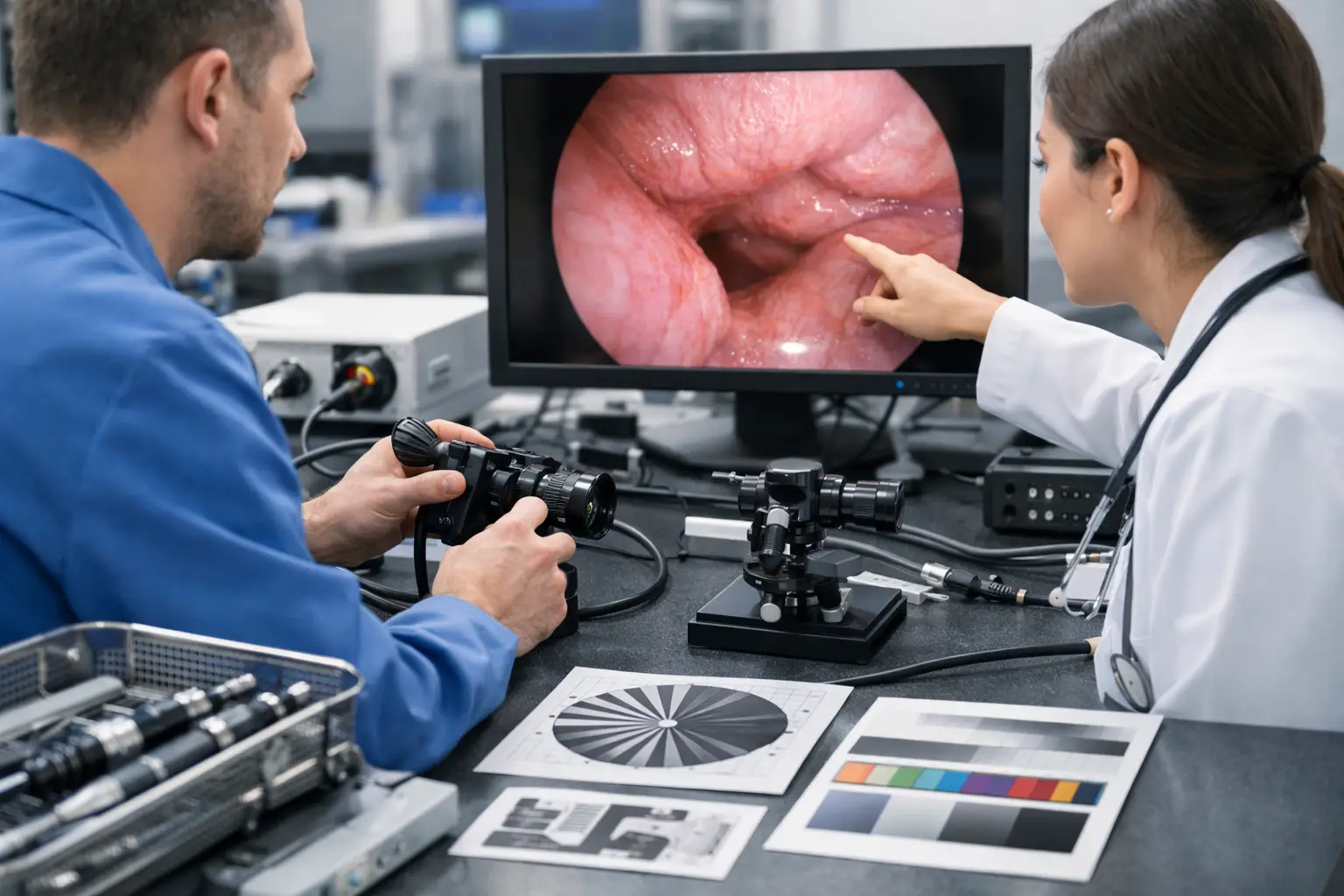
A good validation plan combines objective measurement with task-based evaluation. Resolution charts can quantify center and corner sharpness, while distortion charts reveal geometric behavior and uniform targets expose vignetting. These tests should be performed at multiple working distances, not only at the nominal focus point.
Also evaluate low-light noise, color reproduction, dynamic range, illumination uniformity, and specular-reflection behavior. For industrial products, test representative defects and materials. For medical products, validation protocols should reflect the intended imaging environment and applicable regulatory requirements.
Production testing needs practical pass/fail limits. Inspect every module for obvious contamination, dead pixels, focus, and illumination operation, then use sampling plans for deeper optical characterization where appropriate. Establish golden samples, calibrated fixtures, and traceable test images. This gives procurement teams confidence that a qualified sample can be reproduced at volume.
The most effective next step is to send the camera-module team representative target images, minimum feature size, working distance, required diameter, interface, frame rate, and environmental conditions. Those inputs turn image clarity from a vague request into an engineering specification that can be built, tested, and scaled.