A USB camera can enumerate correctly, stream video, and still fail the actual application if exposure, gain, white balance, or focus cannot be controlled as expected. For product teams building robotics, medical, security, and industrial devices, knowing how to configure UVC controls is the difference between a camera that simply works on a bench and one that delivers repeatable image output in the field.
UVC, or USB Video Class, provides a standardized way for a host system to discover and operate many camera functions without requiring a proprietary driver. The standard reduces software integration time, but it does not make every control universally available. The camera firmware, image signal processor, USB descriptors, operating system, and application layer must all agree on what the device supports.
Start With the UVC Control Architecture
A UVC camera exposes functions through control units defined in its USB descriptors. In practical terms, controls commonly fall into two groups: camera-terminal controls and processing-unit controls.
Camera-terminal controls are generally tied to image capture behavior. These may include exposure time, iris, focus, zoom, pan, tilt, roll, and privacy functions. Processing-unit controls typically adjust the image after capture, including brightness, contrast, hue, saturation, sharpness, gamma, white balance, gain, power-line frequency, and backlight compensation.
Not every module supports every item in the UVC specification. A fixed-focus USB camera, for example, should not advertise autofocus controls. Likewise, a module with a sensor or ISP that uses automatic exposure but does not support manual shutter configuration cannot provide reliable manual exposure control just because a host application expects it.
Before software work begins, define the controls the finished device actually requires. An industrial barcode reader may need locked exposure and gain to prevent motion blur and image-to-image variation. A telemedicine device may prioritize auto white balance, anti-flicker operation, and stable skin-tone rendering. A robotics platform may require manual focus, exposure priority, and a method for recovering known settings after startup.
Verify What the Camera Really Advertises
The host can only configure controls that the camera declares and implements. Start by inspecting the UVC descriptors and querying control capabilities rather than assuming support from a generic product specification.
On Linux, V4L2 tools can list supported controls, valid ranges, defaults, current values, and menu options. Windows applications can inspect standard camera properties through the applicable Media Foundation, DirectShow, or Windows camera API path. On other operating systems, the available framework may expose a smaller subset of the camera’s advertised UVC capability.
For each critical control, verify five details:
- Whether the control is present and enabled in the UVC descriptor
- Its minimum, maximum, step size, default value, and current value
- Whether it operates in automatic or manual mode
- Whether the host driver and application framework expose it
- Whether the camera applies the setting consistently during streaming
That last point deserves careful testing. Some image signal processors accept a command but apply it only after the stream restarts. Others take effect on the next frame, while certain controls are overwritten by an automatic algorithm unless auto mode is disabled first.
A disciplined validation record should capture the requested value, returned value, measured image effect, firmware version, host operating system, and USB speed. This record becomes valuable during pilot builds and later supplier qualification, especially when the same product ships across multiple hardware platforms.
How to Configure UVC Controls in the Right Order
Control order matters because many settings depend on one another. Setting exposure while auto exposure remains enabled is a common source of confusion. The host may accept the requested number, then the firmware immediately changes it to maintain the target brightness.
First, select the intended video format, resolution, frame rate, and USB transport mode. These parameters establish the camera’s timing limits. At 30 frames per second, exposure time cannot usually exceed the frame period without reducing the effective frame rate or changing sensor behavior. Higher resolutions and uncompressed formats also increase USB bandwidth requirements, particularly on USB 2.0 designs.
Next, set automatic modes deliberately. If your application needs a fixed image response, disable auto exposure, auto white balance, autofocus, and automatic gain behavior where supported. If automatic operation is the requirement, configure the related parameters that remain available, such as exposure priority, power-line frequency, or white-balance temperature range.
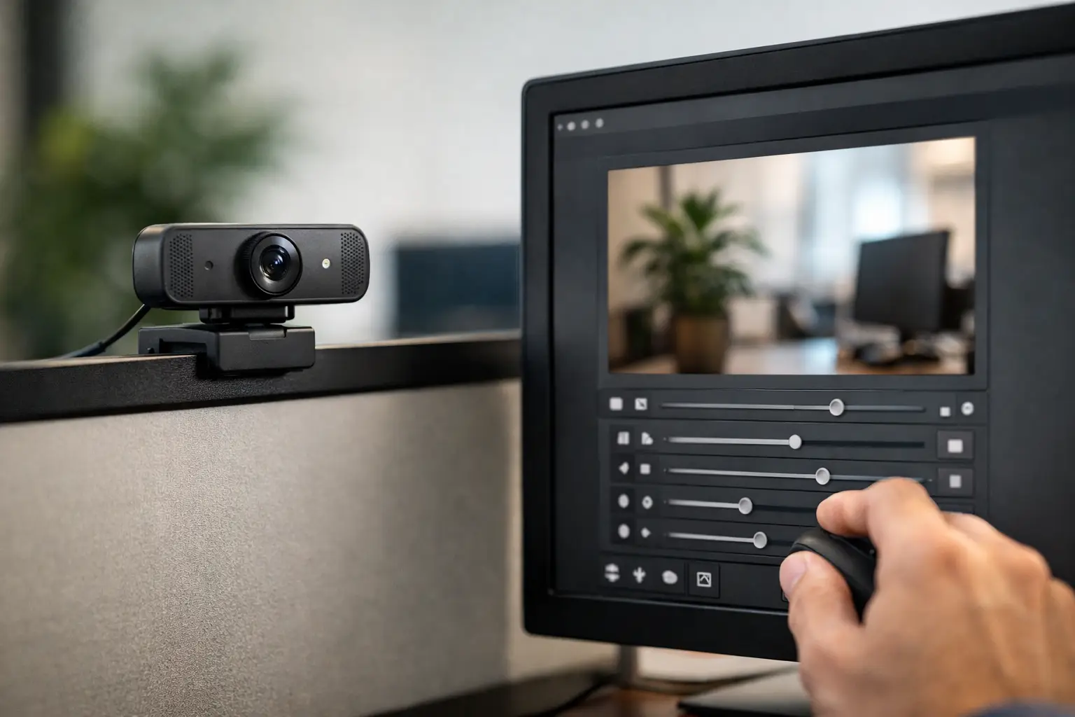
Then apply manual values in a controlled sequence. A practical sequence is exposure first, gain second, white balance third, and image enhancements last. Exposure sets the amount of light captured. Gain increases signal amplification but also raises visible noise. White balance should be evaluated under the application’s actual illumination, not only under office lighting. Brightness, contrast, sharpness, and gamma should be tuned conservatively because aggressive processing can remove shadow detail, create halos, or reduce machine-vision feature reliability.
Finally, read each setting back from the device and capture test images. Do not treat a successful API return code as proof that the result is correct. Compare image brightness, color, noise, motion blur, and frame timing against acceptance criteria.
Configure Exposure and Gain for the Application
Exposure is often represented by the host API in units that are not immediately intuitive. The UVC specification and host framework may use device-specific scaling, logarithmic values, or time units defined by the implementation. Confirm the unit with the module documentation and validate it using controlled light and motion tests.
For moving objects, choose the longest exposure that still prevents unacceptable blur. Then use illumination, aperture, sensor sensitivity, and gain to reach the desired signal level. Raising gain is convenient, but it is not free. It can degrade low-contrast edge detection, introduce chroma noise, and create inconsistent results in inspection algorithms.
For 50 Hz or 60 Hz LED and fluorescent environments, configure power-line frequency compensation where available. The correct setting depends on the local electrical environment and lighting driver behavior. It may reduce visible flicker, but it cannot correct poor-quality lighting or an exposure time that conflicts with the source modulation frequency.
Configure White Balance, Focus, and Processing Controls
White balance should match the use case. Auto white balance is useful where lighting changes frequently, such as mobile inspection equipment or consumer-facing devices. However, it can introduce frame-to-frame color shifts that are undesirable for color measurement, medical visualization, and product inspection. In those cases, lock the white balance after calibration under a defined light source.
Focus has similar trade-offs. Autofocus improves usability when working distance changes, but focus hunting can delay capture and create inconsistent frames. Fixed-focus optics are often the more stable choice for a controlled working distance. If a variable-focus module is required, test focus movement, settle time, near-limit behavior, and recovery after power cycling.
Controls such as sharpness, denoise, backlight compensation, and gamma should be treated as image-processing decisions, not cosmetic defaults. For human viewing, moderate enhancement can improve perceived quality. For computer vision, the best setting may be minimal processing and a predictable image pipeline. The correct choice depends on whether the camera output feeds an operator, an AI model, a metrology algorithm, or a recording system.
Handle Operating System Differences Early
UVC promotes compatibility, but host platforms do not expose controls in identical ways. A control available through Linux V4L2 may be hidden by a Windows application layer. A system API may group several standard controls under one property, while a third-party video application may expose only brightness, contrast, and exposure.
For this reason, validate the camera on the actual target host, operating system version, USB controller, and application framework. Test cold boot, warm reconnect, sleep recovery, repeated start-stop streaming, and settings persistence. If the device is intended for managed deployments, confirm whether the application should restore preferred control values at every launch instead of relying on camera-side retention.
Vendor-specific capabilities may be implemented through UVC extension units. These can provide access to ISP registers, HDR modes, trigger behavior, sensor test patterns, or specialized processing functions. Extension units are useful when standard UVC controls are insufficient, but they require custom host software and should be documented carefully. They also reduce plug-and-play portability compared with standard controls.
Build Control Configuration Into Production Validation
For OEM programs, UVC configuration is not only a software task. It is a joint camera, optics, firmware, host, and manufacturing requirement. The control map should be frozen alongside sensor selection, lens parameters, resolution, field of view, and mechanical integration.
Define default values at the factory, then specify what the host application may change. Establish pass/fail criteria for exposure response, white-balance stability, focus behavior, flicker performance, and image quality at key operating temperatures. If a custom camera module will be used in multiple regional markets, include lighting and power-frequency conditions in the verification plan.
SincereFirst supports this engineering approach by aligning USB camera module hardware, optics, firmware behavior, and scalable production requirements before volume deployment. A clear UVC control specification reduces integration risk, shortens debugging cycles, and helps ensure that replacement modules behave consistently across production lots.
The most effective configuration is not the one with the most controls enabled. It is the one that gives your device the image behavior it needs, every time it powers on and every time it operates in its real environment.