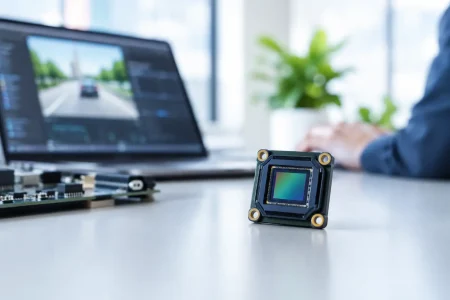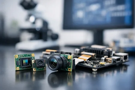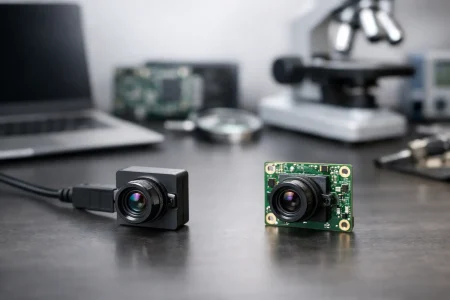
A camera module can stream clean video on an engineer’s bench and still fail when connected to a customer’s Windows PC, Linux edge computer, or embedded Android device. That gap is exactly what a UVC camera compliance guide should prevent. For OEM teams, compliance is not a label added at the end of development. It is a firmware, interface, optical, and host-validation discipline that protects schedule, interoperability, and field reliability.
UVC, or USB Video Class, defines a standardized method for a USB camera to identify itself and deliver video to a host without requiring a proprietary camera driver. It is widely used in industrial cameras, medical peripherals, robotics, conferencing equipment, inspection devices, and smart terminals. The value is clear: faster integration and broader host support. The engineering work is less simple. A UVC module must expose accurate descriptors, negotiate supported streams correctly, respond predictably to control requests, and remain stable under real cable, power, bandwidth, and operating-system conditions.
What UVC Compliance Actually Means
UVC compliance is often misunderstood as a single certification or pass/fail document. In practice, it has several layers. First, the device implementation must conform to the applicable USB Video Class specification and USB protocol requirements. Second, its advertised capabilities must match its actual behavior. Third, the finished product may need separate USB, EMC, electrical safety, wireless, medical, or market-specific approvals depending on where and how it will be sold.
A UVC camera that works with a generic host driver is not automatically certified by USB-IF, nor does it automatically satisfy FCC, CE, UKCA, medical-device, or product safety requirements. Procurement teams should keep these workstreams separate. UVC class compliance addresses USB video interoperability. Regulatory compliance addresses the finished device and its target market.
For most OEM programs, the practical target is straightforward: the camera must enumerate reliably as a standards-based UVC device, operate using native host support where required, and perform consistently across the intended host platforms. That requirement should be written into the camera module specification before samples are approved.
UVC Camera Compliance Guide: Start With the Right Specification
The fastest way to create integration risk is to specify only resolution, frame rate, and interface type. A request for “1080p USB camera” leaves too much undefined. Compliance depends on the complete stream profile and control behavior.
Define the USB generation first. USB 2.0 can be suitable for compressed 1080p video, lower-frame-rate uncompressed streams, and many compact embedded products. USB 3.0 provides substantially more bandwidth for uncompressed video, higher resolutions, multiple streams, and lower-latency machine-vision workflows. The correct choice depends on format, frame rate, cable length, host capability, power budget, and cost target. A USB 3.0 interface does not compensate for an underpowered host or a poorly designed cable path.
Next, document every supported video mode: resolution, pixel format, frame interval, compression method, and endpoint transfer type. Common formats include YUY2, MJPEG, NV12, H.264, and sometimes vendor-defined formats. Each format has trade-offs. Uncompressed YUY2 simplifies host-side decoding but consumes significant bandwidth. MJPEG reduces transport bandwidth and is broadly supported, but image quality and CPU load vary by implementation. H.264 can be efficient for long cable runs or network-connected systems, yet host support, licensing considerations, and latency behavior must be reviewed for the target application.
The module must advertise only modes it can deliver consistently. A mode that appears in a descriptor but drops frames, changes timing, or produces unstable exposure behavior under sustained operation is not a commercially acceptable capability.
Descriptors Are the Contract With the Host
USB descriptors tell the host what the device is, what controls it supports, and which stream configurations it can use. Incorrect descriptors are one of the most common reasons a camera works on one computer but not another.
The device descriptor, configuration descriptor, interface association, VideoControl interface, VideoStreaming interface, endpoints, format descriptors, frame descriptors, and color-matching information need to be internally consistent. The host uses this information to select an alternate setting, negotiate a probe and commit control sequence, and allocate bandwidth. Small inconsistencies can cause enumeration failures, missing resolutions, black video, or an unsupported-format message.
Pay particular attention to frame intervals. If a camera advertises 30 fps, its timing fields and actual stream delivery must support 30 fps at the stated resolution and format. The same discipline applies to maximum frame size, maximum payload transfer size, and endpoint capability. These values should be validated from firmware data, not copied from a similar module.
Verify Control Behavior, Not Just Video Output
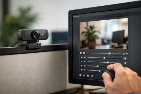
A production UVC camera must do more than transmit images. It needs to handle standard control requests correctly. Depending on the implementation, these may include exposure, gain, white balance, focus, zoom, brightness, contrast, hue, saturation, sharpness, power-line frequency, and privacy controls.
Not every control needs to be supported. The issue is accuracy. If a control is not available, the descriptors and request responses must state that cleanly. If automatic exposure is supported but manual exposure is not, that relationship needs to be correctly represented. If a host reads a control range, default, resolution, or current value, the response must be valid and stable.
This matters in industrial and medical-adjacent products where repeatable imaging is more valuable than consumer-style automatic adjustment. An inspection device may require fixed exposure and gain to preserve measurement consistency. A portable diagnostic accessory may require a controlled white-balance behavior under a defined LED spectrum. In these cases, UVC standard controls may be sufficient, or a documented extension-unit approach may be necessary. The decision should be made early because proprietary extensions can reduce plug-and-play simplicity.
Test on the Hosts Your Customers Will Use
No single test application proves UVC interoperability. Windows, Linux, macOS, Android, and embedded Linux distributions differ in camera frameworks, power management, format preferences, and control handling. Even two Windows systems can behave differently because of chipset, USB controller, security policy, and application stack differences.
A meaningful validation plan should cover the actual commercial environment. Test direct connection and any planned hub, dock, extension cable, or adapter. Test cold boot, warm reconnect, repeated plug cycles, sleep and wake behavior, and host restart during streaming. Test each advertised mode for sustained operation, not only a short preview window.
For cameras used in automation or unattended equipment, include long-duration streaming tests at the highest expected bandwidth and worst expected ambient temperature. Watch for frame drops, USB resets, image artifacts, exposure drift, memory leaks, and recovery behavior after a cable disturbance. A camera that recovers without manual intervention can prevent expensive service calls in deployed systems.
Account for Electrical and Mechanical Reality
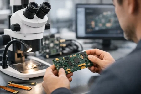
UVC software behavior cannot be separated from hardware design. Signal integrity, cable quality, connector retention, grounding, power stability, and thermal management all affect whether a camera behaves as a compliant device in a finished product.
USB 3.0 designs are especially sensitive to routing and cable performance. High-speed signal paths require controlled impedance, suitable connectors, proper shielding, and careful layout. For compact camera modules, FPC length, board stacking, metal enclosure contact, and nearby switching noise can change results between prototype and production. An engineering sample with a short laboratory cable is not proof that a final enclosure will pass stable streaming tests.
Power also deserves specific attention. Camera sensors, image signal processors, autofocus actuators, LEDs, and onboard compression all create transient demand. If the host port or product power rail cannot support startup and peak current, symptoms may look like a firmware issue: intermittent enumeration, frozen frames, or random disconnects. Measure the complete module behavior across startup, streaming, control changes, and temperature.
Build a Release Gate Before Mass Production
Before approving a UVC camera module for volume production, establish a release record that engineering, quality, and sourcing teams can review together. It should include the approved firmware revision, sensor and lens configuration, USB interface version, supported stream table, control table, host test matrix, cable assumptions, and known limitations. This prevents silent substitutions and makes field issues traceable.
A practical release gate should also confirm these five items:
- Descriptor validation shows no structural errors or unsupported claims.
- Every advertised resolution, format, and frame rate has passed sustained streaming tests.
- Required UVC controls return correct ranges, defaults, and current values.
- Target operating systems and customer applications have been tested on representative hardware.
- The final cable, enclosure, power design, and thermal condition have been evaluated, not only the bare module.
For customized programs, retain golden samples and lock the bill of materials once validation is complete. Sensor revisions, lens changes, ISP tuning updates, and connector substitutions can affect color, timing, current consumption, or USB behavior. A capable manufacturer should provide revision control, sample confirmation, and production consistency alongside camera design support.
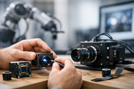
SincereFirst supports this approach by aligning UVC camera module selection, firmware configuration, optical design, and manufacturing control with the actual host and application requirements. That is particularly valuable when an off-the-shelf USB camera must be adapted for a compact robot, industrial terminal, medical accessory, or dedicated imaging instrument.
The most productive next step is to turn your intended user experience into a testable camera requirement: name the host platforms, list the required video modes, define the lighting and operating conditions, and identify the recovery behavior your product needs. Once those details are clear, UVC compliance becomes a measurable engineering target rather than a last-minute integration risk.