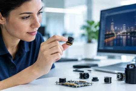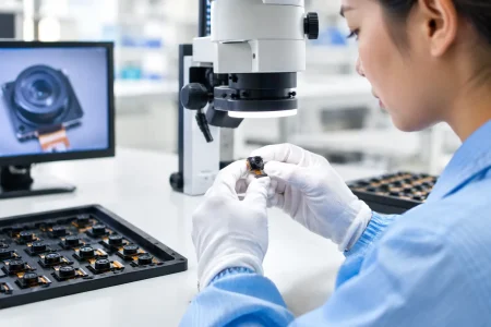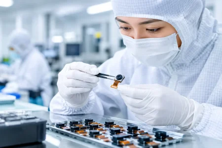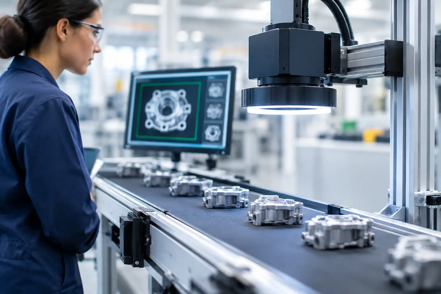
A failed inspection image rarely starts with software. It often starts with a camera module that was selected for resolution alone, an optic that cannot hold focus across the working distance, or an interface that cannot deliver frames when the production line needs them. Machine vision succeeds when the entire imaging chain is designed around the decision the machine must make.
For OEMs, system integrators, and industrial equipment builders, that distinction has direct commercial consequences. A vision system that detects a defect in the lab but drifts under factory lighting, vibration, heat, or line-speed variation creates rework, false rejects, and delayed launches. The right approach is to define the inspection task first, then engineer the camera, optics, illumination, processing, and mechanical integration around it.
What Machine Vision Actually Does
Machine vision converts optical information into an actionable result. A camera captures an image, processing hardware analyzes it, and the system returns a decision such as pass or fail, position correction, code read, object count, measurement, or alert. The application may use conventional rule-based algorithms, deep learning models, or both. The image quality still sets the ceiling for every downstream method.
In a packaging line, the task may be confirming that a label is present and correctly positioned. In electronics assembly, it may be inspecting solder joints or verifying connector placement. A robot may use vision to locate randomly oriented parts before picking them. Medical and endoscopic devices use compact imaging modules to present fine detail in confined spaces. These applications share a need for dependable image capture, but their technical requirements differ sharply.
Resolution, for example, is only useful when it produces enough pixels across the smallest feature that matters. A system checking a 0.2 mm scratch needs different sensor, lens, and working-distance calculations than one reading a large carton barcode. Higher resolution can increase processing load, storage requirements, bandwidth demand, and cost. It is a design variable, not an automatic upgrade.
Start With the Inspection Decision
Before comparing camera modules, define what the system must see, how accurately it must see it, and how quickly it must respond. This stage prevents expensive overdesign and reveals constraints that a datasheet cannot answer.
The first question is feature size. Determine the smallest defect, edge, code element, or measurement point the system must identify. Next, establish the field of view and working distance. Together, these values determine the pixel density and lens focal length required. The acceptable measurement tolerance should also be clear. Detecting the presence of a cap is one task; confirming its alignment within a tight tolerance is another.
Speed matters just as much. A moving part can blur during exposure, even when a camera provides a high frame rate. Short exposure times may require stronger or strobed illumination. A global shutter sensor is often preferred when imaging fast-moving objects because it captures the entire frame at once. Rolling shutter sensors can be cost-effective for static scenes or controlled motion, but motion distortion must be evaluated honestly.
The final operating environment completes the requirement. Consider ambient light changes, reflective surfaces, temperature, vibration, dust, washdown exposure, available mounting space, and cable routing. Compact embedded systems may need a small MIPI or DVP camera module. Industrial computers may favor USB 3.0 or other high-bandwidth interfaces. The best interface depends on processor architecture, cable distance, frame-rate demand, software support, and production serviceability.
The Machine Vision Imaging Chain
A camera module is essential, but it is one part of a connected system. Weak performance at any point in the chain can make a capable sensor appear inadequate.
Sensor selection: sensitivity before headline resolution
Sensor format, pixel size, shutter type, frame rate, dynamic range, and low-light performance influence whether the image contains usable inspection data. Larger pixels can improve light collection, which is valuable in short-exposure applications. A monochrome sensor may provide better contrast and effective resolution for edge inspection, measurement, and certain code-reading tasks, while color imaging is necessary when hue or color consistency is part of the decision.
Dynamic range becomes critical when bright metal, dark housings, and printed markings appear in one scene. If highlights clip or shadows lose detail, software cannot recover information that was never captured. High dynamic range techniques can help, but they can also introduce complexity when objects move or timing is tight.
Optics: the component that defines usable detail
A sensor cannot compensate for an unsuitable lens. Lens choice governs field of view, distortion, sharpness, depth of field, and the amount of light reaching the sensor. For dimensional measurement, low-distortion optics and careful calibration are often more valuable than extra megapixels. For deep scenes or variable part height, depth of field may become the main constraint.
Lighting and optics must be designed as a pair. A backlight can produce crisp silhouettes for gauging. Dark-field illumination can reveal scratches, embossed features, and surface defects. Diffuse light can reduce glare on shiny objects. There is no universal lighting method because defect visibility depends on material, surface geometry, color, and the inspection objective.
Interface and processing: protect the image data
The camera interface must move the required image data at the required speed without creating an integration burden that delays the product. MIPI CSI-2 is widely used in embedded platforms where compact size and direct processor connection matter. USB camera modules are practical for many industrial PCs, prototypes, and systems that benefit from standard connectivity. USB 3.0 provides more bandwidth than USB 2.0 for higher-resolution or higher-frame-rate use cases, while UVC compatibility can simplify host-side deployment where standard video support is appropriate.
Bandwidth calculations should include pixel format, resolution, frame rate, overhead, and any compression strategy. A prototype may work with a short cable and a single camera, then fail when multiple cameras share a bus or when the final enclosure adds electrical noise. Validate the intended production architecture early, including host processor load, thermal behavior, cable lengths, trigger timing, and firmware control.
Custom Integration Is Often the Real Requirement
Standard camera modules accelerate evaluation, but many commercial products need changes before production. The physical envelope may require a different board shape, FPC length, connector orientation, mounting hole pattern, or heat-management approach. The optical stack may need a specific lens, IR filter, focal position, or fixed focus distance. A medical, robotics, or industrial device may also require controlled illumination, shielding, or specialized housing integration.
This is where supplier capability should be judged beyond a catalog. A qualified imaging partner can help align sensor selection, optical design, PCB layout, interface configuration, mechanical constraints, and manufacturing test requirements. Fast samples are valuable, but sample speed without design-for-manufacturing discipline can simply move risk into the production phase.
SincereFirst supports this process with embedded camera modules, optical imaging components, and customized vision development for applications that need both engineering flexibility and scaled supply. For buyers, the practical objective is not merely finding a module that powers on. It is securing an imaging design that can be validated, manufactured consistently, and supported through product revisions.
Validate Under Production Conditions, Not Demo Conditions
Machine vision projects should be tested with real parts, real defects, and real variation. Include acceptable parts at the limits of tolerance, defective parts with meaningful variation, changes in surface finish, and the lighting conditions expected on the line. A small dataset of perfect samples can make an inspection algorithm look far more capable than it is.
Measure false accepts and false rejects separately. A false accept allows a bad part through; a false reject wastes good product and disrupts throughput. The acceptable balance depends on the application. Safety-critical inspection may prioritize catching every suspect condition, while high-volume packaging may require a lower false-reject rate to avoid excessive stoppages.
Also plan for calibration and maintenance. Focus locks, lens mounts, lighting intensity, sensor position, and mechanical alignment can change over time. If an operator must recalibrate the system, make the procedure clear and repeatable. If the device will be deployed across multiple lines or facilities, define acceptance criteria that production and quality teams can use consistently.
The most effective next step is to turn the inspection challenge into a short engineering brief: target feature size, field of view, working distance, speed, lighting conditions, interface, mechanical envelope, and expected production volume. That document gives an imaging team the information needed to build a camera solution that makes the right decision long after the first demonstration.