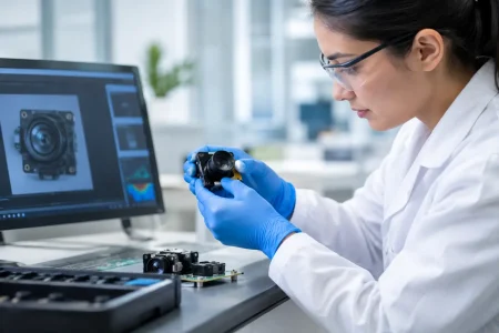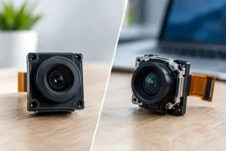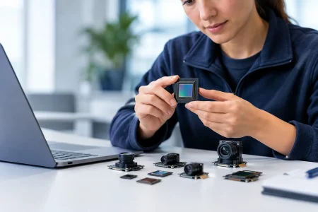

To calibrate autofocus camera modules is not simply to make a lens move until an image looks sharp. For an OEM device, calibration establishes the relationship between actuator position, image quality, object distance, and the host system’s autofocus logic. When that relationship is inaccurate, the result can be slow focus acquisition, hunting, weak macro performance, inconsistent units, or field failures that appear only after thermal cycling and extended use.
For robotics, medical devices, security terminals, smart hardware, and industrial vision products, autofocus must perform predictably under defined operating conditions. The calibration process should therefore be designed as part of camera module development and volume manufacturing, not treated as a final inspection task.
What autofocus calibration actually controls
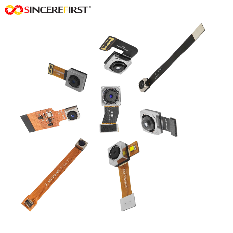
Most compact autofocus camera modules use a voice coil motor, or VCM, to move the lens along the optical axis. The camera driver requests a lens position, while the actuator moves toward that position using a position code, Hall sensor feedback, or an open-loop movement model. Calibration converts those electrical commands into useful optical behavior.
At the hardware level, the process commonly establishes lens travel limits and a repeatable home or reference position. It may also characterize Hall sensor offset, actuator response, and the usable focus range. These values prevent the lens from driving into a mechanical stop and help the system reach the same focus location across repeated cycles.
At the imaging level, calibration identifies where sharpness peaks at known target distances. A module intended to read labels at 150 mm needs a different focus priority from a conference camera expected to hold faces sharp from 0.5 m to several meters. The sensor, lens, actuator stroke, F-number, pixel size, and target field of view all influence the final focus curve.
Software is the third part of the equation. Contrast-detection autofocus, phase-detection autofocus, and hybrid approaches need parameters that match the module’s real optical response. Search step size, confidence thresholds, reversal logic, settling time, and scene-change handling all affect user-visible performance. A well-built module can still focus poorly if the host algorithm uses generic settings.
Define the use case before calibrating autofocus camera modules
A focus target without an application requirement is not enough. Before the calibration station is specified, define the working-distance range, minimum acceptable sharpness, focus acquisition time, illumination conditions, and expected subject motion. These choices determine what the factory should measure and what the software should optimize.
Consider a handheld medical imaging accessory. Its priority may be sharp near-field imaging, controlled focus movement, and consistent performance under LED illumination. A warehouse robot may need faster transitions between near packages and distant aisle markers. A smart access terminal may prioritize face distance, low-light stability, and resistance to false focus shifts caused by a patterned background.
The trade-off is straightforward: a wider search range generally takes more time, while a narrow range can be faster but may miss unexpected subject distances. Larger focus steps accelerate a scan but can skip the true sharpness peak. Smaller steps improve precision but increase latency and actuator activity. The correct setting depends on the device function, not on a universal autofocus score.
Build a calibration setup that reflects production reality
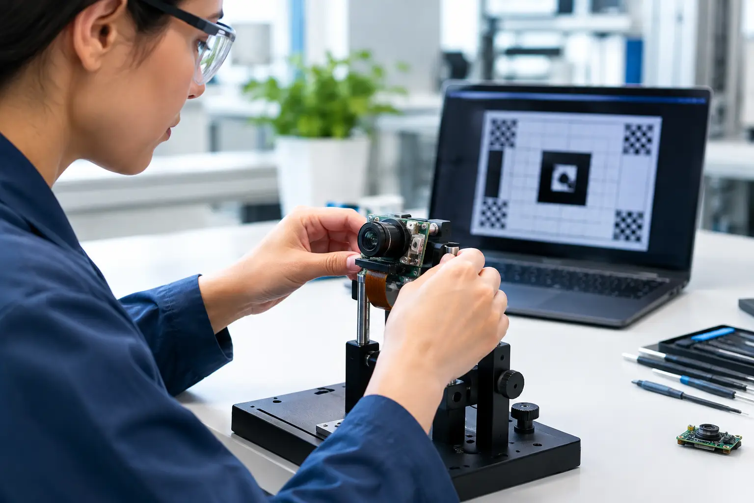
A reliable setup begins with a stable fixture that holds the camera module at a known position and angle. Any tilt between the image plane and the test chart can make one region of the frame appear sharper than another, leading engineers to diagnose a focus issue that is actually a mechanical alignment error.
The optical target should have sufficient contrast and known spatial-frequency content for the lens and sensor being tested. Slanted-edge charts, resolution targets, and application-specific patterns can all be useful. For barcode readers or document scanners, use representative printed materials in addition to laboratory targets. A module can score well on an ideal chart yet struggle with the low contrast, glare, or repetitive texture present in actual deployments.
Illumination must also be controlled. Light level, color temperature, flicker, and reflections can change the autofocus metric. If the end product uses infrared illumination, an IR-cut filter, or mixed lighting, the calibration and validation plan should account for those conditions. Visible-light focus and infrared focus may differ because of chromatic focal shift, especially with compact optics.
The test system needs traceability. Record module serial number, sensor and lens configuration, actuator lot where applicable, station ID, software version, measured calibration data, and pass-fail results. This information is valuable when analyzing a field issue or comparing performance across production batches.
A production method to calibrate autofocus camera modules
The most effective process separates mechanical reference calibration from image-quality calibration, then verifies autofocus behavior at the system level. The exact sequence varies with the actuator architecture and ISP pipeline, but the following flow is practical for volume programs.
First, initialize the module and allow the actuator to settle. Measure or establish its reference position. With closed-loop VCMs, this often includes confirming Hall sensor behavior and mapping position feedback to the requested code range. With open-loop designs, the process relies more heavily on controlled endpoint movement and repeatable drive conditions.
Next, identify the valid mechanical travel range. The lens must not operate at positions where it contacts mechanical limits, produces unacceptable image quality, or becomes unstable. A small guard band on either side of the usable range helps account for normal unit variation, temperature change, and component aging.
Then capture images at specified target distances while sweeping the lens through the valid range. Calculate a focus metric, such as edge sharpness or modulation transfer response, for the required regions of interest. The peak positions create a focus map that shows which actuator codes correspond to intended object distances. For modules with field curvature or slight optical decentering, measure center and off-axis regions rather than relying on one central patch.
After that, program the module or host configuration with the calibrated values. Depending on the design, these values may reside in module memory, the image sensor’s nonvolatile memory, the ISP configuration, or the host processor. Confirm that the production data format, firmware version, and checksum process prevent the wrong calibration file from being applied to a unit.
Finally, run a closed-loop autofocus test. Start from deliberately defocused positions, command focus at multiple distances, and measure acquisition time, final sharpness, and repeatability. A lens that reaches a sharp image once is not necessarily calibrated well. It should return to the required performance after repeated near-to-far and far-to-near transitions.
Validate beyond the bench
Bench calibration proves that a module meets a controlled condition. Product validation determines whether it will behave correctly in the device. Both are necessary.
Test the integrated camera with the actual processor, driver, ISP tuning, enclosure, and illumination system. Mechanical stress from mounting, heat from nearby electronics, and lens cover glass can change optical performance. A cover window may introduce reflections, reduce contrast, or shift focus if its thickness, tilt, or material differs from the design assumption.
Temperature testing deserves particular attention. VCM behavior, lens barrel dimensions, adhesive properties, and sensor noise change as temperature changes. Validate focus at the operating extremes defined by the product specification, not only at room temperature. For mission-critical devices, repeat autofocus cycling after vibration, drop, humidity, and aging tests as appropriate to the application.
It is also wise to validate difficult scenes: low contrast, low light, bright backlight, reflective surfaces, and moving subjects. These tests reveal whether the autofocus algorithm needs confidence gating, exposure coordination, a restricted search region, or fallback behavior such as holding the last confirmed focus position.
Design calibration for scale, not only for samples
A manual focus-tuning procedure may be acceptable during early prototyping, but it becomes a bottleneck and a quality risk in production. Scalable calibration uses repeatable fixtures, automated image capture, controlled lighting, software-driven analysis, and clear pass-fail limits. Cycle time matters, but reducing it should not remove the measurements that protect field reliability.
Tolerance analysis should begin before mass production. Sensor placement, lens assembly, VCM stroke, optical alignment, and cover-glass variation all contribute to focus variation. If the design has very little optical margin, calibration can compensate only so far. The better solution may be to revise the lens specification, actuator selection, mechanical stack-up, or acceptable working-distance requirement.
This is where an experienced camera module manufacturer can shorten development risk. SincereFirst supports module selection, optical configuration, autofocus tuning, and production-oriented test planning so that a prototype focus result can be translated into controlled manufacturing output.
Information to give your camera module supplier
A supplier can calibrate more efficiently when the program starts with measurable requirements. Provide the target working distances, field of view, resolution requirement at each distance, autofocus time target, lighting conditions, operating temperature range, interface and processor platform, and the final mechanical stack around the camera.
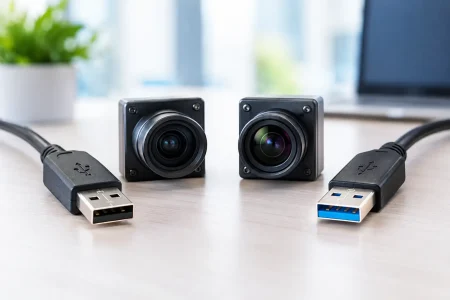
Also specify whether the host will run autofocus control or whether the module solution should provide the required driver and tuning data. For MIPI camera modules, compatibility with the chosen ISP and operating system can be as consequential as the optical calibration itself. For USB and UVC modules, confirm how autofocus commands and status are exposed through the intended software stack.
The best calibration plan is one that produces evidence your engineering, quality, and procurement teams can evaluate: defined test distances, repeatable focus metrics, traceable production records, and clear acceptance limits. That turns autofocus from a subjective visual impression into a controlled imaging capability your product can rely on.