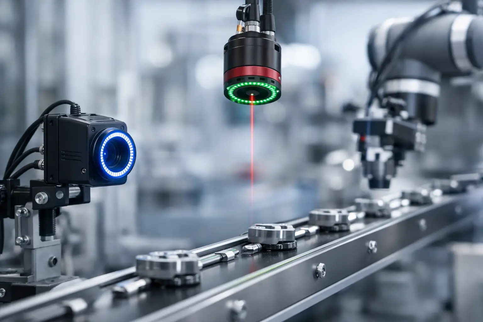
A rejected part at the end of a high-speed line is expensive. A missed defect that reaches a customer is worse. Selecting the top machine vision sensors for factories is therefore not a matter of choosing the highest resolution or the newest interface. The sensor must capture the defect, code, edge, or position feature that matters at the required line speed, under the lighting and mechanical conditions of the actual station.
For OEMs, automation builders, and system integrators, the best choice starts with the inspection task. Pixel size, shutter architecture, sensitivity, dynamic range, interface bandwidth, and module design all affect whether an imaging system performs consistently after deployment. This guide compares the sensor types that matter most in industrial production and explains where each one fits.
What Makes a Vision Sensor Right for a Factory?
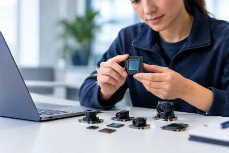
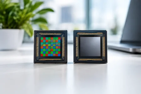
In this context, a machine vision sensor is the image sensor inside a camera or camera module, rather than a simple photoelectric presence sensor. The sensor converts light into image data; its performance sets the ceiling for inspection accuracy, usable speed, and lighting tolerance.
A practical specification begins with the smallest feature that must be detected. If a scratch is 0.2 mm wide and the required field of view is 200 mm, the system needs enough pixels across that field to represent the scratch with meaningful contrast. Resolution alone is not enough, however. A 20-megapixel sensor can still fail a fast-moving application if its shutter produces motion distortion or its interface cannot move frames quickly enough.
Lighting should be considered at the same time as sensor selection. A monochrome sensor paired with controlled red, blue, or near-infrared illumination can reveal contrast that a color sensor may dilute. Conversely, color imaging is necessary when the inspection decision depends on label color, wire color, produce maturity, or paint matching.
Top Machine Vision Sensors for Factories by Application
Global shutter CMOS sensors for high-speed motion
Global shutter CMOS sensors expose every pixel at the same instant. This prevents the skew, stretching, and partial-image artifacts associated with rolling shutter capture when objects move quickly or when the camera is mounted on a moving robot.
They are typically the first choice for pick-and-place verification, conveyor inspection, robotic guidance, electronic component inspection, and code reading at speed. A global shutter sensor also makes pulsed strobe lighting easier to use because the entire frame receives the same short exposure.
The trade-off is that global shutter devices may offer lower resolution, lower peak sensitivity, or a higher cost than comparable rolling shutter sensors. Those limits are often acceptable when stable geometry matters more than maximizing pixel count. For a line running hundreds of parts per minute, eliminating motion artifacts generally has more value than adding unused megapixels.
Rolling shutter CMOS sensors for controlled, high-resolution imaging
Rolling shutter CMOS sensors read rows sequentially rather than capturing the full image at one time. They are widely available, cost-effective, and offered in a broad range of resolutions. In a stationary inspection cell or a slow-moving process, they can be an efficient solution for detailed surface inspection, document capture, packaging verification, and laboratory-style quality checks.
The risk appears when relative motion is present. A rotating cap can look oval, a conveyor edge can lean, and a fast robot arm can become distorted. Carefully timed lighting, short exposure settings, and controlled motion can reduce the effect, but they do not change the underlying readout method.
Rolling shutter is not a lower-quality choice by default. It is a task-specific choice. When the part is fixed, the camera is stable, and resolution or cost drives the project, it can provide excellent imaging performance.
Monochrome sensors for contrast-critical inspection
Monochrome sensors record intensity rather than color channels. Because every pixel receives the available light without a color filter array, monochrome imaging often delivers higher effective detail and better sensitivity than an equivalent color sensor. It is particularly effective for dimensional measurement, print inspection, barcode and Data Matrix reading, edge detection, and defect detection on metal, plastic, textiles, and semiconductor materials.
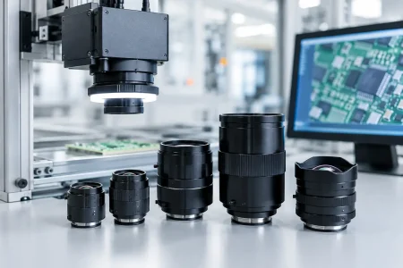
Monochrome sensors become even more capable when paired with narrow-band illumination. For example, red illumination can suppress certain printed backgrounds, while infrared can help distinguish inks, adhesives, moisture patterns, or surface conditions that are difficult to evaluate under white light. The optical stack still matters: lens resolution, working distance, depth of field, and illumination angle can determine whether a small defect is visible.
Color CMOS sensors for appearance and classification
Color sensors are required when hue, saturation, or color placement is part of the pass-fail decision. Typical uses include package artwork verification, food sorting, beverage cap inspection, assembly checks for colored wires or components, and cosmetic surface grading.
For factory use, evaluate color accuracy under the lighting that will be installed, not under office lighting. White balance, color correction, and exposure control must be repeatable. A color camera module that produces attractive images for a human operator may still be unsuitable if the measured color varies from shift to shift.
Higher-resolution color sensors are often appropriate for one-camera inspections with a large field of view. Still, more pixels increase bandwidth and processing demand. An inspection station may perform better with two focused cameras than with one high-resolution camera forced to cover every feature.
Near-infrared and extended-spectrum sensors for material visibility
Some inspection targets are not best seen in visible light. Near-infrared-capable sensors can support applications such as agricultural sorting, fill-level checks, print and security marking verification, and material differentiation. With the right illumination and optical filter, NIR imaging can expose patterns hidden by visible color or reduce distracting surface graphics.
These systems need application testing. Sensor quantum efficiency, lens transmission, filter selection, and the wavelength of the illuminator must be matched. A standard camera module may see some NIR wavelengths, but an engineered solution is needed when the inspection result depends on repeatable spectral response.
High dynamic range sensors for reflective and mixed-light scenes
Factory scenes frequently combine bright metal, dark cavities, transparent film, and uneven ambient light. High dynamic range sensors retain more detail across those bright and dark regions, helping prevent clipped highlights and blocked shadows.
HDR is useful for automotive parts, polished housings, welding-area monitoring, electronics inspection, and packaging lines with glossy materials. It is not a replacement for proper illumination. Multi-exposure HDR can also create artifacts if the object moves between exposures. For fast production lines, a well-designed lighting setup and a sensor with good native dynamic range may be preferable to aggressive HDR processing.
Interface and Camera Module Decisions Matter
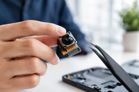
The sensor is only one part of the imaging chain. A well-matched module must transfer images without becoming a bottleneck, fit the available space, and remain stable through production.
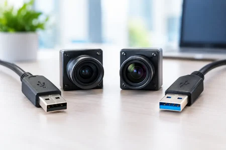
USB 3.0 camera modules are practical for industrial PCs and prototype systems that need high frame rates with straightforward integration. USB 2.0 suits lower-bandwidth monitoring and simpler inspection tasks. MIPI CSI-2 modules are often selected for embedded processors, smart cameras, mobile robots, and compact edge AI devices because they reduce size and can support efficient high-speed image transfer. DVP interfaces remain relevant in cost-sensitive embedded designs and legacy processor platforms.
For OEM development, confirm the image signal processor path early. Sensor output format, supported frame rates, driver availability, auto-exposure behavior, and synchronization capability can affect the final result as much as the datasheet resolution. Hardware trigger input and flash output are particularly valuable when multiple cameras or strobes must be synchronized with encoder-driven motion.
A Practical Selection Process for Factory Projects
Start by documenting the feature to inspect, the field of view, working distance, line speed, and acceptable false-pass and false-reject rates. Then determine the required pixels across the smallest feature. This prevents the common mistake of specifying resolution from a catalog rather than from measurement needs.
Next, decide whether motion requires global shutter. If the part, tool, or camera moves during exposure, global shutter should be the default starting point. Select monochrome or color based on the inspection signal, then test lighting before committing to a final sensor. A controlled light source often improves performance more than a sensor upgrade.
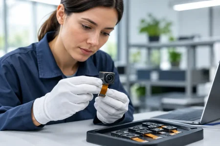
Finally, validate the complete assembly under real conditions: production speed, vibration, temperature, reflective materials, dirty lenses, and normal part variation. Sample images taken on a clean bench rarely represent a factory line. This validation step is where customized optics, housing design, cable routing, trigger timing, and image tuning become commercially important.
SincereFirst supports this process with standard and customized camera modules for embedded industrial imaging, combining sensor selection, optical integration, interface matching, and scalable manufacturing. For projects moving from prototype to volume production, a supplier should be able to preserve the validated imaging configuration rather than force a redesign when demand increases.
The best sensor is the one that produces a repeatable decision at the line rate you need. Define that decision first, prove it with the right light and optics, and then build the camera module around a sensor architecture that can keep producing the same result shift after shift.