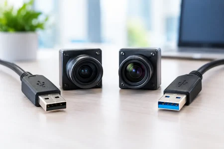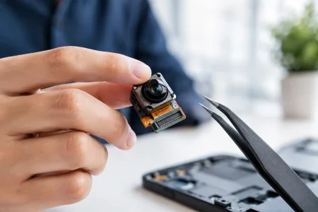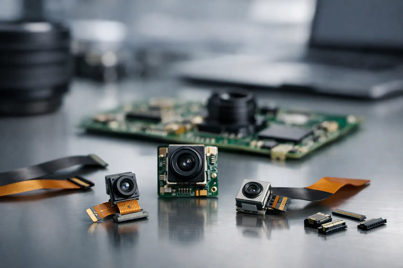
A connector can be the smallest component in a camera assembly and still determine whether the product reaches production on schedule. This camera module connector selection guide helps OEM teams evaluate the electrical, mechanical, and manufacturing factors behind a dependable camera-to-mainboard connection. The right choice protects image data, fits the enclosure, supports repeated assembly, and remains sourceable through the product lifecycle.
For embedded vision products, connector selection should begin alongside camera module selection, not after the sensor, lens, and PCB layout are fixed. A high-resolution MIPI camera, a compact endoscope module, and a USB camera module each create different interface, shielding, pin-count, and assembly requirements. Treating the connector as an engineering decision early can prevent redesigns, intermittent image faults, and unnecessary tooling changes later.
Start With the Camera Interface
The connector must first match the electrical interface and signal requirements of the camera module. This sounds basic, but interface labels alone do not define a compatible interconnect. Pin assignments, lane count, voltage rails, control lines, grounding strategy, and cable length all matter.
MIPI CSI-2 camera modules commonly use fine-pitch FPC or board-to-board connectors because they carry high-speed differential lanes in compact equipment. The number of MIPI data lanes, the required clock lane, I2C control signals, reset, power, and ground pins determine the actual pin count. A 2-lane module and a 4-lane module can use physically similar connector families while requiring completely different pin maps.
DVP camera modules generally need more parallel data connections and clock signals. They can be practical for legacy embedded platforms or lower-speed applications, but their larger signal count may require a wider FPC connector or a different board layout. USB camera modules use USB 2.0 or USB 3.0 signal pairs and may also need power, shielding, and auxiliary control provisions depending on the design. USB 3.0 creates a more demanding signal-integrity environment than USB 2.0, particularly when the cable or flex length increases.
Before approving a connector, engineering teams should confirm the complete interface definition: signal names, pin order, voltage levels, lane configuration, impedance targets, and grounding locations. Do not assume a connector with the same number of contacts is interchangeable. Incorrect pin mapping can damage the module or produce failures that only appear during high-speed image transmission.
Camera Module Connector Selection Guide: Mechanical Fit
Electrical compatibility is only half the decision. The connector also has to survive the space claim, installation sequence, and service conditions of the final device.
Pitch and contact count
Pitch is the center-to-center spacing between contacts. Fine-pitch connectors save PCB area and support compact FPC camera modules, but they demand tighter fabrication and assembly control. In a small robotics controller, handheld medical device, or smart lock, a 0.3 mm or 0.5 mm pitch may be necessary. In a larger industrial enclosure, a wider pitch may provide easier handling and better field-service practicality.
Contact count should include every required signal plus adequate grounds. Ground contacts are not spare positions. They provide current return paths, help control noise, and support differential-pair performance. For high-speed interfaces, the connector pinout should preserve the intended signal-to-ground relationship rather than simply packing signals into consecutive positions.
Orientation, height, and cable exit
Top-contact and bottom-contact FPC connectors are not equivalent. The flex cable’s exposed contacts must face the correct direction, and the cable must exit in a way that avoids sharp bends or interference with batteries, housings, heatsinks, and other PCBs.
Connector height is equally relevant. A low-profile horizontal connector can reduce total device thickness, while a vertical board-to-board connector may suit stacked assemblies. Evaluate the assembled camera, cable, connector, adhesive, strain-relief feature, and enclosure together. A connector that fits on a bare PCB can still fail the finished product’s height or bend-radius requirement.
Retention and mating cycles
A zero-insertion-force FPC connector with a flip-lock or slide-lock actuator is widely used for compact camera integration. It offers a low-force insertion process, but the locking mechanism must be accessible to operators and protected from accidental opening. For equipment subject to vibration, shock, or frequent service, retention force deserves close attention.
Mating-cycle rating should match real use. A connector inside a sealed, nonserviceable imaging device may only be mated during production and repair. A camera head, inspection tool, or development platform can be connected many more times. Specifying a connector with unnecessarily high mating-cycle performance can raise cost and size, while underspecifying it can create premature service failures.
Protect Signal Integrity Before Image Problems Appear
Image artifacts, dropped frames, camera enumeration failures, and unstable preview streams are often blamed on the sensor or software first. The interconnect may be the cause, especially with MIPI CSI-2 and USB 3.0 systems.
High-speed differential pairs need controlled impedance through the cable, connector, and PCB routing. Connector selection should be coordinated with the flex-cable stack-up and the host-board layout. Long stubs, uneven pair routing, poor return paths, and unnecessary adapters can degrade margins. The camera may work in a short laboratory setup but fail when the production cable is installed in a metal housing beside motors, displays, or wireless radios.
Cable length is a practical dividing line. For a very short board-to-board connection, a compact connector system may be sufficient. For a remote camera position, such as a robot arm, vehicle cabin, agricultural machine, or endoscope handle, the design may need better shielding, strain relief, or a different transmission architecture. A connector cannot compensate for an unsuitable cable design.
Electromagnetic compatibility also matters. Grounding tabs, shield connections, connector shell design, and cable shield termination should be reviewed as a system. The best approach depends on the enclosure, regulatory targets, nearby noise sources, and the camera interface speed. There is no single connector style that solves EMC for every imaging device.
Select for Production, Not Just the Prototype
A connector that works on an engineering bench may be costly or difficult to build at volume. Manufacturing evaluation should cover component availability, PCB land pattern tolerance, solder-joint inspection, actuator handling, automated placement capability, and rework process.
Fine-pitch connectors require disciplined SMT control. Pad design, solder paste volume, coplanarity, and placement accuracy affect yield. If the connector uses an FPC lock, operators need a repeatable insertion procedure that confirms the flex is fully seated and the actuator is correctly closed. Partial insertion can create intermittent contacts that are difficult to detect in a basic functional test.
For volume programs, specify an approved connector family and a controlled alternate strategy where possible. Second-source availability can reduce supply risk, but alternates must be qualified for dimensions, locking behavior, contact plating, signal performance, and pin compatibility. A nominally equivalent replacement can alter assembly reliability or interfere with the housing.
This is particularly relevant for medical, industrial, security, and smart infrastructure equipment with long product lives. Connector lifecycle planning should consider supplier continuity, end-of-life notices, minimum order quantities, and the ability to support repairs years after launch.
Match the Connector to the Application Environment
Environmental exposure changes the selection criteria. A camera inside a consumer device may prioritize thinness and cost. An industrial vision camera near machinery may need stronger retention, wider operating-temperature performance, and better resistance to vibration. A medical imaging assembly may require compact geometry, controlled materials, repeated cleaning compatibility at the system level, and strict traceability.
Endoscope camera modules create an especially constrained case. Their small diameters, tight bend requirements, and repeated mechanical movement place significant demands on cable and termination design. The connector at the controller end still needs enough retention and shielding to maintain stable imaging, even when the distal module is extremely compact.
For outdoor security, agricultural, and smart-city products, consider condensation, dust, temperature cycling, and service access. The connector may sit inside a sealed enclosure, but the cable route and nearby seals determine whether moisture or mechanical stress reaches the interconnect. Add strain relief where movement, pull force, or vibration can be transmitted into the FPC termination.
Define the Connector Specification Early
A useful connector specification should be specific enough for sourcing, layout, production, and quality teams to act on without interpretation. It should define the interface, pinout, pitch, contact count, orientation, mounting style, height limit, lock type, cable thickness range, plating requirement, mating-cycle target, operating environment, and approved manufacturer status.
It should also identify the camera module revision and flex-cable drawing that the connector supports. This avoids a common integration error: changing the module cable or PCB layout while retaining an old connector part number in the bill of materials.
SincereFirst supports camera module and connector matching as part of a complete embedded imaging evaluation, helping OEM teams align sensor selection, FPC design, interface requirements, and scalable manufacturing before the design is released.
The best connector is rarely the smallest or lowest-cost option in isolation. It is the one that preserves the camera interface, fits the mechanical design, can be assembled repeatedly at target volume, and remains available for the life of the product. Confirm those conditions before layout freeze, and the camera connection becomes a controlled part of the system rather than a late-stage risk.