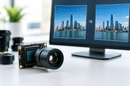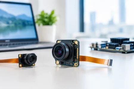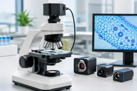

A camera module can pass every bench test in an engineering lab and still create a serious medical-device compliance problem. The gap usually appears when the module moves from prototype to production: a sensor revision changes low-light noise, an autofocus setting shifts, a supplier substitutes an IR filter, or the imaging data package is too thin to support the finished device’s risk file. FDA camera module guidance begins with a clear principle: FDA regulates the finished medical device and its intended use, not a camera module as an isolated commodity. Yet the module is often a safety-critical component, and its design, controls, and traceability must stand up to the device manufacturer’s quality system.
For medical OEMs, endoscope developers, and imaging-system integrators, the practical objective is not to find a universally “FDA-approved camera module.” That is not how FDA clearance or authorization works. The objective is to select and control an imaging component that helps the finished device meet its performance claims, risk controls, manufacturing requirements, and applicable regulatory pathway.
What FDA Camera Module Guidance Means in Practice
There is no single FDA document that prescribes one sensor, resolution, optical stack, or interface for every medical camera application. Expectations depend on the finished device’s classification, intended use, clinical setting, and the consequences of degraded or misleading images. A module used for consumer wellness imaging creates a different risk profile from one used in an endoscope, surgical visualization system, wound assessment device, or diagnostic workflow.
The FDA Quality Management System Regulation, effective February 2, 2026, updates 21 CFR Part 820 and incorporates ISO 13485:2016 by reference with additional FDA requirements. For camera module sourcing, the relevant outcome is straightforward: the finished-device manufacturer needs documented evidence that purchased components are suitable, controlled, and consistently produced.
That evidence should connect the module to the device’s design inputs. If a product claim depends on detecting small tissue features, reading a diagnostic test strip, or maintaining visibility in a minimally invasive procedure, the camera module specification cannot stop at resolution. The specification must define the imaging characteristics that affect the claim and the clinical risk.
Start With Intended Use, Not a Sensor Datasheet
A sensor datasheet is necessary, but it does not define fitness for a medical device. The engineering team should first translate intended use into measurable imaging requirements. This normally includes field of view, working distance, depth of field, resolution at the object plane, frame rate, exposure behavior, color accuracy, sensitivity, dynamic range, distortion, and illumination compatibility.
For a fixed-focus inspection camera, stable focus across a known distance range may matter more than high pixel count. For an endoscope module, small diameter, low heat generation, flexible cable routing, moisture protection, LED compatibility, and reliable color reproduction may carry greater weight. In a diagnostic imaging application, repeatability between units and over temperature can be more important than the best image produced by a single engineering sample.
The key question is: what image failure could cause the user to make the wrong decision or fail to complete the intended task? That question ties camera performance to risk management. It also prevents procurement from selecting a module based only on price, nominal resolution, or a reference image captured under ideal lighting.
Define performance at the system level
A camera module is only one part of an imaging chain. Lens selection, optical filter transmission, illumination spectrum, image signal processor tuning, firmware, cable length, display behavior, compression, and image-processing algorithms can all change the final output. A module may be electrically compatible with a host platform while producing unacceptable color, noise, latency, or artifacts in the finished device.
For this reason, verification should use representative system hardware and intended-use conditions. Test across realistic distances, lighting levels, temperatures, motion, target materials, and cleaning or sterilization exposures where applicable. If software enhancement is used to improve visibility, assess the combined module-and-algorithm output rather than treating the sensor result as the final answer.
Build a Supplier File That Supports Qualification
A medical-device manufacturer remains responsible for its finished device, but a capable camera module supplier can materially reduce qualification effort. The supplier should be able to provide consistent technical records, controlled manufacturing processes, and clear communication when a change may affect the product.
A useful supplier package generally includes these distinct records:
- A controlled module specification covering sensor model, lens, filter, interface, electrical characteristics, dimensions, operating conditions, and optical performance targets.
- Manufacturing and inspection information, including incoming controls, assembly controls, functional testing, lot identification, and final inspection criteria.
- Reliability and environmental test data relevant to the intended application, such as thermal cycling, vibration, cable flexing, ESD, humidity, or operating-life testing.
- Material and process information needed for the device assessment, including cleaning compatibility, biocompatibility considerations for patient-contacting assemblies, and applicable substance declarations.
- A documented change-notification process covering sensor end-of-life, lens or filter substitutions, firmware revisions, process changes, and manufacturing-site changes.
Not every project needs the same depth of documentation. A module installed behind a sealed, non-patient-contacting housing has different evidence needs than a camera assembly integrated into a reusable medical endoscope. The device maker should scale supplier controls to risk, while avoiding the mistake of treating lower-cost components as lower-risk merely because they are common in consumer electronics.
Control Changes Before They Reach Production
Component change is one of the most frequent causes of imaging drift. Semiconductor availability, sensor revisions, lens coating updates, adhesive substitutions, and image-tuning changes can alter performance without changing a module’s outward appearance. An uncontrolled substitution may affect color balance, sensitivity, signal timing, electromagnetic behavior, or mechanical fit.
A supplier agreement should identify what constitutes a notifiable change, how much advance notice is required, and which changes require customer approval before shipment. The device manufacturer should then define how it will evaluate the impact. Minor packaging changes may only require review. A sensor die revision, optical prescription change, or firmware update may require repeat verification, software regression testing, risk-file updates, and assessment of regulatory reporting or submission impact.
Traceability matters here. Lot-level identification allows the manufacturer to connect finished devices to incoming camera modules, inspection results, and change records. If a field issue occurs, this connection supports efficient investigation and containment instead of a broad, expensive production hold.
Avoid Common Compliance Shortcuts
The phrase “medical grade” is not a substitute for documented requirements. It can describe an internal supplier program, but it does not establish that a component is appropriate for a specific FDA-regulated device. Likewise, an ISO certificate from a supplier is useful evidence of quality-system maturity, not proof that the finished product will meet FDA requirements.
Another shortcut is relying on sample images alone. Attractive images do not show unit-to-unit consistency, performance under low illumination, tolerance to electrical noise, or behavior after environmental stress. Engineering teams should establish acceptance criteria before evaluating samples and retain the test evidence that supports selection.
Finally, do not separate camera hardware decisions from software decisions. If the system uses auto exposure, auto white balance, denoising, distortion correction, or AI-assisted image interpretation, module selection and image pipeline validation must be managed together. The more the software influences a clinical image or user decision, the more disciplined the configuration and verification process must be.
Design for Manufacturing, Service, and Supply Continuity
The most compliant camera module is not necessarily the best production choice if it has a fragile supply chain, limited second-source options, inconsistent lead times, or an architecture that cannot be serviced. Medical devices often have long market lives, so lifecycle planning should begin during module selection.
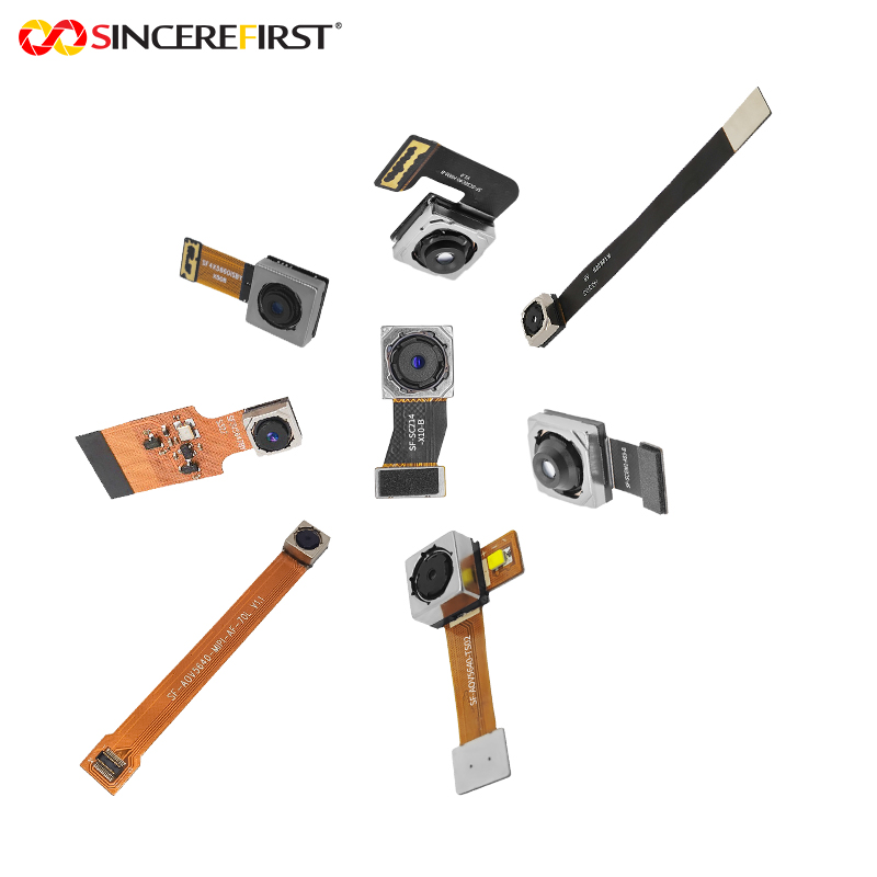
Select interfaces and mechanical designs that can be manufactured repeatedly at volume. MIPI, USB, UVC, DVP, and custom FPC configurations each have trade-offs involving bandwidth, cable length, host compatibility, electromagnetic performance, and integration space. For compact medical and endoscopic applications, optical alignment, cable strain relief, module heat, and assembly yield deserve the same attention as image quality.
An experienced manufacturing partner can contribute by providing rapid prototypes, engineering samples built to controlled specifications, optical customization, and scalable production records. SincereFirst supports this approach with embedded camera modules and customized imaging assemblies for device teams that need to move from feasibility testing to repeatable production without losing control of the imaging baseline.
A well-chosen camera module does more than create a clear image. It gives the finished-device team a controlled foundation for verification, risk management, supplier qualification, and long-term manufacturing confidence.